

GAMMA RAY 3 FT AMPLITUDE CHL TRACE 5 FT VDL
USING A SECTOR BOND LOG OR A RADIAL BOND LOG, CAN YOU DISCUSS THE WELL’S IN PLACE CEMENT PLACEMENT PATTERN, THE PERCENTAGE OF CEMENT PLACEMENT, THE STAGE OF THE WELL’S IN PLACE CEMENT CURING FOR THE WELL’S UNIQUE CEMENTING RECIPE AT THE TIME THE LOG WAS RUN, THE RANGE OF VALUES FOR THE WELL’S CASING SIZE, WEIGHT, AND CEMENT COMPRESSIVE STRENGTH FOR A SATISFACTORY CEMENT JOB?
WIRELINE CREWS AREN’T NORMALLY FAMILIAR WITH THE DRILLING AND CEMENTING OF THE WELL, BUT ARE CALLED TO THE WELL SIGHT TO LOG AND PRESENT THE LOG THAT GRADES THE DRILLING AND CEMENTING PROCEDURES FOR THE WELL. I THINK, THE MOST IMPORTANT PART OF BEING SUCCESSFUL IS CONFIDENCE.
BOND LOG INTERPRETATION WITH THE CHL - FOR THE UP OR CEMENT EVALUATION MEETING AT THE WELL SIGHT
FROM THE JOB TICKET OR THE COMPLETION PROCEDURE - THE PERORATION INTERVAL
A SATISFACTORY CEMENT JOB - NO FOUR LINE CONTINUOUS LOOKING CHANNELS ABOVE OR BELOW THE PERFORATION INTERVAL
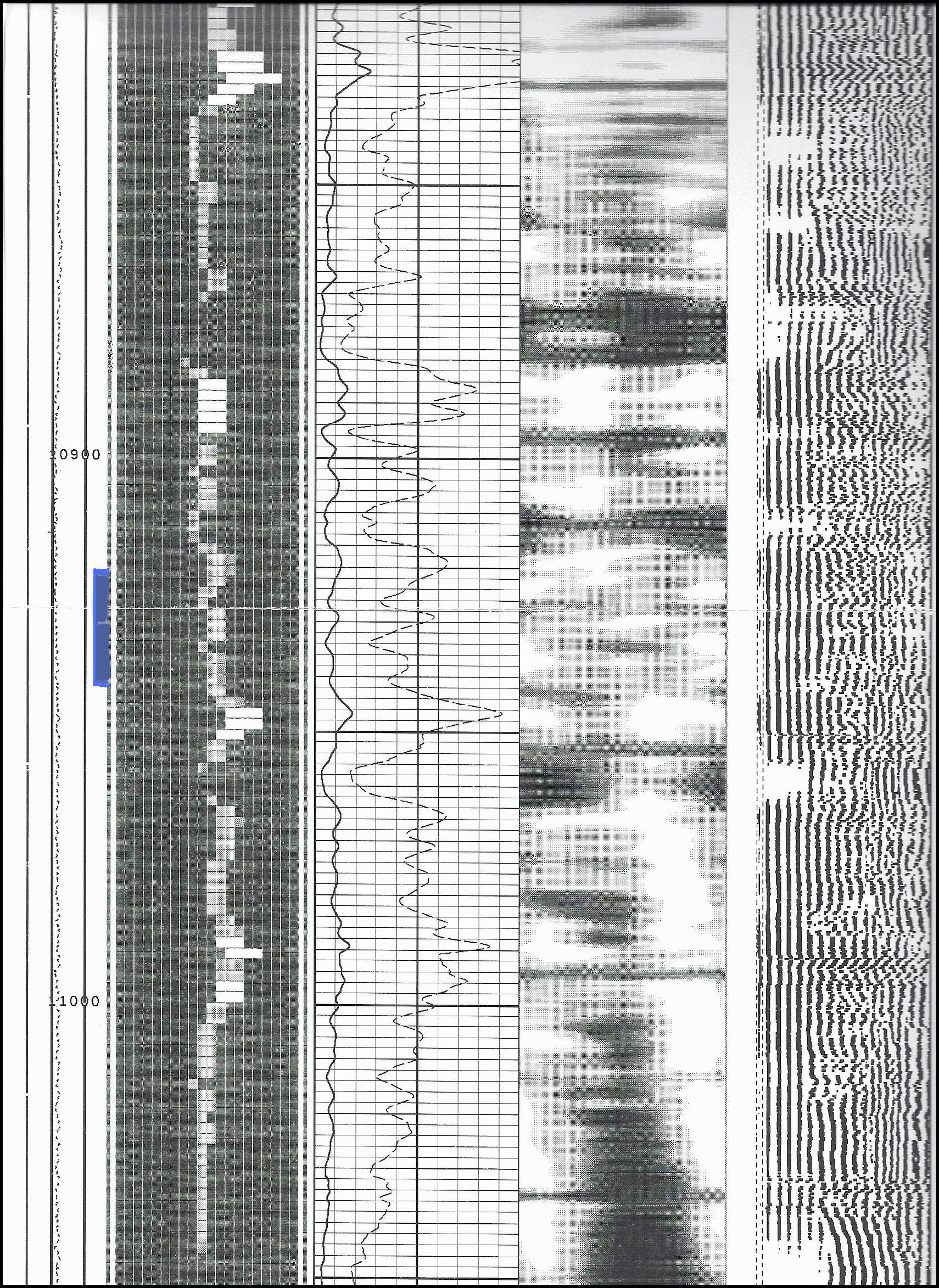
CHL TRACE 3 FT AMPLITUDE SECTORS 5 FT VDL
CONFIDENCE - SUPPORTED BY OVER FOUR HUNDRED PRODUCTION WELLS
CEMENT EVALUATION and THE CEMENT JOB -
The Cement Job -
the Vocabulary
the Knowledge
the Understanding
the Confidence
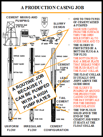
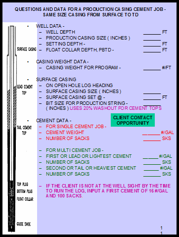
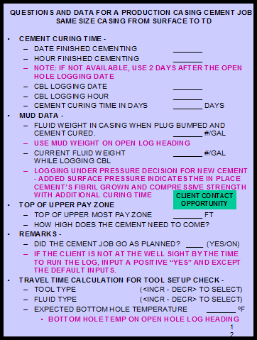
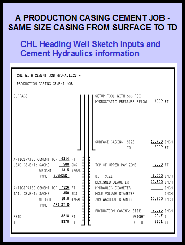
PRODUCTION CASING CEMENT JOB -
PRODUCTION CASING IS THE SAME SIZE CASING FROM THE WELL'S TD TO SURFACE
1. WHERE IS THE CEMENT?
2. HOW MUCH LOG DO I RUN TO LOG THE CEMENT TOPS?
LINER CEMENT JOB -
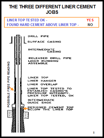
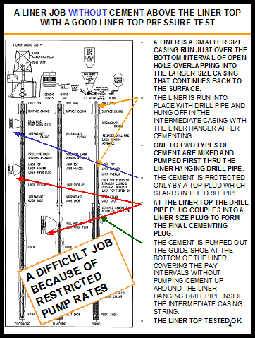
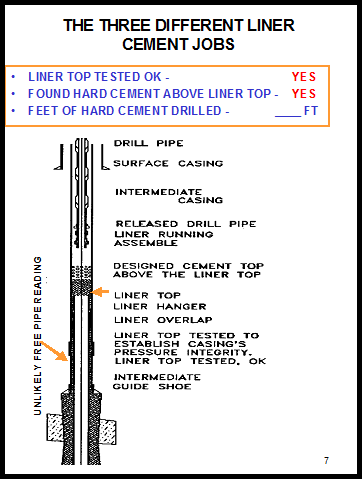
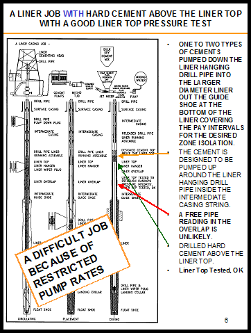
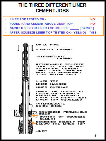
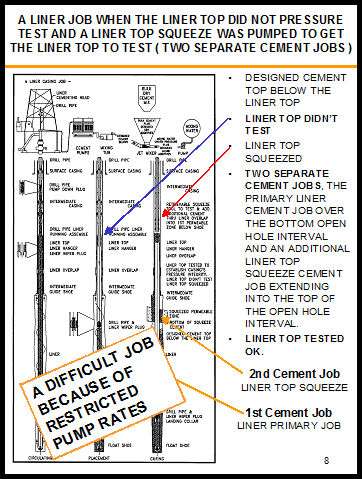
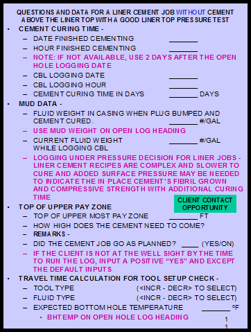
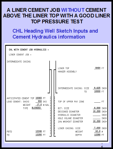
THE LINER AND CEMENT HANGER ARE RUN ON DRILL PIPE TO COVER THE BOTTOM SECTION OF THE WELL. THE LINER IS RUN FROM THE WELL'S TD WITH AN OVERLAP INTO THE INTERMEDIATE CASING STRING. AFTER THE LINER IS CEMENTED AND THE HANGER SET, THE LINER TOP IS TESTED TO VERIFY THE INTEGRITY OF THE CASING STRING.
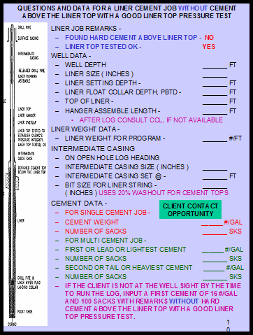
1. WHERE IS THE CEMENT? - THREE LINER CEMENT JOBS.
2. RUN THE LOG FROM THE WELL'S PBTD TO A HUNDRED FEET ABOVE THE LINER TOP.
AN EDITORIAL -
The Cementing Companies The Cementing Companies main focus is to help design and laboratory test each cement recipes, sell cement and the necessary designed additives for the unique cementing recipe designed for each well, furnish the personnel and the specialized equipment to deliver and mix and pump the cement job at the well sight. The Cement Company’s pre-job presentation emphasizes the importance of planning the correct pump rate needed for the desired Cement Placement for each Well’s unique conditions. But the Cement Company does not follow up after the job, to inquire about the actual in place cement placement and placement pattern, or the actual in place cement curing for the Well’s Designed Cementing Recipe, but Drilling does not ask that they do.
The Logging Companies cement evaluation package main focus, as directed by the industry, is toward the up or down cement evaluation meeting immediately after running the well’s cement evaluation log to determine, with the rig waiting, if the cement job is satisfactory or unsatisfactory for zone isolation thru the critical intervals for the well’s production zones which determines the sequence of the rest of the completion steps to continue finishing the completion of the well. This focus does not normally include indicated in place cement placement and cement placement pattern analysis or measured in place cement curing analysis.
Cement Placement ( Where is the Cement? ) and Cement Placement Patterns –
When the Well is being drilled, the rotating Drill Pipe is whipping around in the borehole making the Path of Lease Resistance for the drilling fluid the same through out the Wellbore and Annular Hole Area, and the Path of Lease Resistance in not that important.
All the time the Casing is being run, the Well’s drilling fluid is not being circulated or moved until the Casing is in place.
After the Casing is in place the Rig’s Mud Pumps are hooked up and the Drilling Fluid circulation is started. The Casing is not moving like the Drill Pipe was and the Path of Lease Resistance controls the flow of the moving circulating Drilling Fluid. The Well's circulation pattern is established
When the Casing is somewhat centered, the Drilling Fluid column is moving uniformly around the Casing. When the relationship of the Casing and Borehole chances, the Drilling Fluid pattern follows the path of lease resistance.
With the Drilling Fluid being pumped, the mixed Cement slurry is staged into the pumping system. The Mixed Cement is going to continue in the Well's flow pattern, establish by the circulating Drilling Fluid Column. The heavy, thick Cement column has little chance of reaching the turbulent flow necessary to change the Drilling Fluid flow pattern established by the position of the Casing and the Borehole.
When the Casing is somewhat centered there is Cement all the way around the Casing. When the Casing Borehole relationship create restrictive flow in the Borehole which restricts the flow of the moving Cement with a chance for Bypassed Well Fluids, there is not Cement all the way around the Casing creating the need for knowledgeable Cement Evaluation thru the Well's Zones of Critical Isolation.
The Circulation Pattern is set for the Cement job –
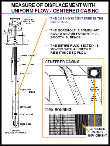
When the Casing is somewhat centered in a somewhat round hole, the entire fluid column is moving, because the Path of Lease Resistance is similar all round the Casing – Slug Flow and 100% Cement Placement
When the Casing is ex-centered to one side, the fluid column is only moving on the high side of the borehole, because that is the Path of Lease Resistance around the Casing. The low side of the Casing has restricted flow with a chance for Bypassed Well Fluids and a Continuous Channel.
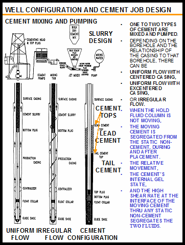
In Well intervals where the entire fluid column is not moving, the Moving Cement is segregated from the Static Non-cement, During and After Placement. The Relative Movement, the Cement’s internal gel state, and the high shear rate at the interface of the Moving Cement thru any Static Non-cement segregates the two fluids.
When the well was drilled with a rifle barrel irregular shape borehole, the Well’s Fluid Flow Path is irregular flow with a rotating moving flow pattern. In Well intervals where the entire fluid column is not moving, the fluid column is going to follow that rifle barrel irregular shape, because that is the Path of Lease Resistance around the Casing with a chance for Bypassed Well Fluids, but not long Continuous Channels.
Knowing the above, the result is three Cement Placement Patterns that can be seen and documented by the CHL Trace presentation
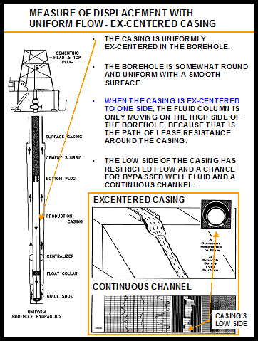
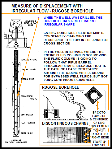
FOR ADDITIONAL CONFIDENCE AND UNDERSTANDING FOR YOUR CEMENT EVALUATION PRESENTATION THRU THE CRITICAL INTERVAL FOR ZONE ISOLATION, USE THE FIGURE BELOW, FOR CEMENT PLACEMENT ( Where is the Cement? ) AND CEMENT PLACEMENT PATTERN SUPPORT
1. UNIFORM FLOW WITH CENTERED CASING SLUG FLOW AND 100% CEMENT PLACEMENT
2. UNIFORM FLOW BUT WITH UNCENTERED CASING WITH THE POSSIBILITY OF BYPASSED WELL FLUID ON THE LOW SIDE OF THE CASING AND THE CHANCE OF A CONTINUOUS CHANNEL PATTERN
3. IRREGULAR FLOW WITH A ROTATING MOVING FLOW PATTERN WITH A CHANCE FOR BYPASSED WELL FLUID, BUT NOT LONG CONTINUOUS CHANNELS

The Chemistry of In Place Cement Curing –
The Cement Slurry is a complex mixture of an artificial material made by burning a blend of limestone and clay complicated with the impurities of the area it was mined from. Plus, the impurities of the water it was mixed with. Plus, the chemistry of the Drilling Mud and the Wellbore.
What is the Cement's Measured In Place Cement Curing Analysis at the Time the Log was run?


THE CHL TRACE AND CHL HEADING -
A CEMENT EVALUATION LOG EVERYONE IN THE ROOM CAN UNDERSTAND, When the Well's Critical Intervals for Zone Isolation are not Logged showing 100% Cured Cment
CHL - Cement Hydraulics Log is a proven, visual, simple, straight forward Cement Evaluation interpretation, using the 3 ft amplitude signal. The CHL identifies the 100% Cement Reading for your casing size, casing thickness, and cement compressive strength and couples it with the interpretation cutoff limit for possible 100% solids, Crystalline Cement, for a consistent interpretation in a twenty line display with shading from Black to Grey to White.
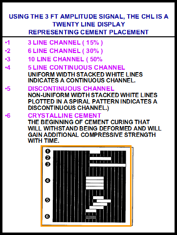

WHEN THE WELL'S CRITICAL INTERVALS FOR ZONE ISOLATION ARE NOT LOGGED SHOWING 100% CURED CEMENT, RANGE OF VALUES FOR A SATISFACTORY CEMENT JOB.
Cement Evaluation is Complex and Controversial, so What are the Range of Values that define the success of your Cement Job? A two millivolt reading always indicates a good Cement Job, but sometimes a ten to fifteen millivolt reading can be a good Cement Job also.
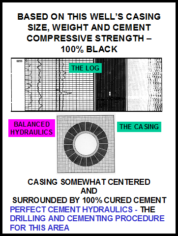
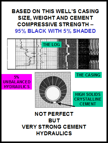
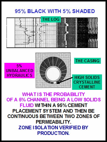
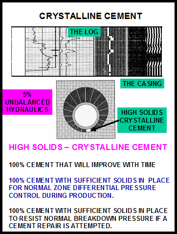
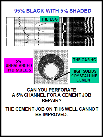
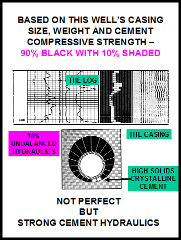
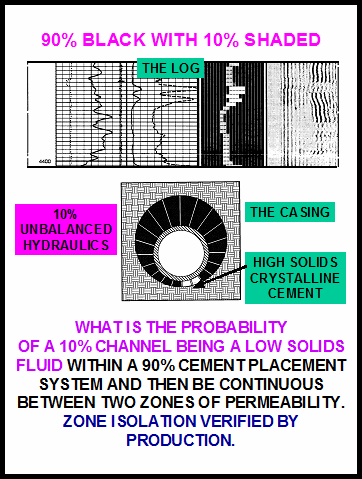
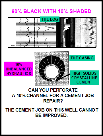
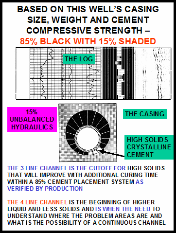
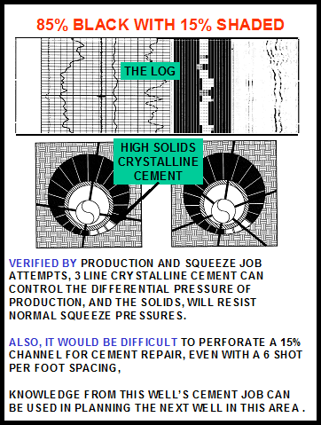
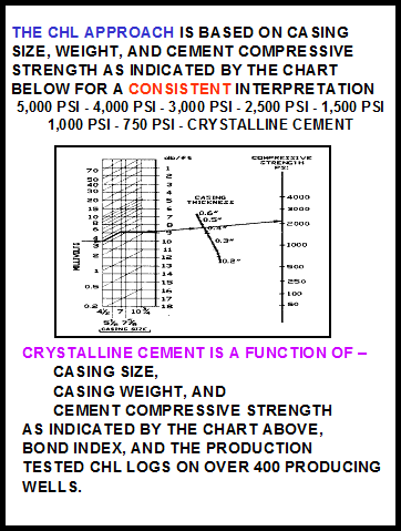
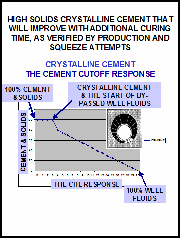
THE CHL CEMENT EVALUATION APPROACH, USING THE RANGE OF VALUES FOR THIS WELL'S CASING SIZE, CASING WEIGHT, AND CEMENT COMPRESSIVE STRENGTH -
A Cement Job with a Somewhat A Cement Job with the Cementing
Centered Casing with Uniform Column Rotating and Spiraling up
Cement Placement and a Fast - the Hole and a Slower Curing 6 Day
Curing 2 day Cementing Recipe - Cementing Recipe with NO Long
A Satisfactory Cement Job. 4 White Line Channels
A Satisfactory Cement Job,
with a Cement that will continue
to Cure and Improve with Additional Time.


THE CHL HEADING is the tool to Understanding and Presenting the CHL. The Confidence to Present and the Understanding the CHL Trace. The Presentation, the Knowledge, and the Understanding of the Well's In Place Cement Pattern and the measured In Place Cement Curing for the Well’s Cementing Recipe adds more confidence to the Well’s Cement Evaluation Presentation.
A Fast Curing Cement Recipe A Slow Curing Cement Recipe
that will Improve with additional Curing Time


OIL WELL CEMENT EVALUATION is POLITICAL
Because the Cement Evaluation Log reflects the quality of the Well Drilled and Cemented and is a direct reflection on the Drilling Department, who Plans and Designs the Drilling of the Well, and Plans and Designs the Cement Job, makes Cement Evaluation Logging very political and controversial and puts the Logging Companies in the middle with more and more complex Cement Evaluation Presentations, that everyone in the room needs extensive training to understand.
The Industry has not insisted that the Cementing Companies and the Logging Companies make the existing Cement Evaluation Packages Technology present and evaluate Cement Placement and Measured In Place Cement Curing as a critical part of the Cement Evaluation Package process to insure that Drilling has this Knowledge and Understanding for the Well's Completion Planning.
The importance of having the knowledge and understanding of Measured In Place Cement Curing, most of the time, is not a critical concern, but knowing that sometimes it is, changes everything.
Drilling, who Plans and Designs the Drilling of the Well, and Plans and Designs the Cement Job, should have the added insight from the Logging Company - Cement Placement and Measured In Place Cement Curing.
Someone in the Well Planning and Approval meeting that routinely evaluates measured In Place Cement Curing and knows and understands that complex Cement Recipes are unique and Cement Curing time needs to be addressed.
OIL WELL CEMENT EVALUATION is COMPLEX AND CONTROVERSIAL AND POLITICAL
For a fee of two hundred dollars -
When the Well’s Critical Intervals for Zone Isolation are not Logged showing 100% Cured Cement, and you are not quit comfortable with your Cement Evaluation Presentation, for support contact Bill Wheelis, phone 1 – 504 – 393 – 0263 and e-mail a pdf file of the Log to wwheelis@cox.net to discuss ( Where is the Cement? ) and the Cement Placement Pattern. To support Your presentation and to discuss the Stage of the Well’s In Place Cement Curing for the Well’s unique Cementing Recipe at the time the Log was run, and the Range of Values for the Well’s Casing Size, Weight, and Cement Compressive Strength for a satisfactory Cement Job, e-mail the Log’s LAS file with depth and the 3 ft amplitude readings for a Log Playback with the addition of the CHL Trace and the CHL Heading.
All communication and data will be kept confidential.
Computalog had the CHL available at the Well Sight as part of their Logging package, and in every Log Off situation, Computalog secured the Client’s Work and his Confidence, when coupled with the Cement’s Job – the Vocabulary, the Knowledge, the Understanding, and the Confidence with a Visual, Simple, Consistent Cement Evaluation from the CHL Trace and CHL Heading to discuss the Well’s Cement Placement ( Where is the Cement? ), the In Place Cement Placement Pattern, the Percentage of Cement Placement, the Stage of the Well’s In Place Cement Curing for the Well’s unique Cementing Recipe at the time the Log was run, the Range of Values for the Well’s Casing Size, Weight, and Cement Compressive Strength for a Satisfactory Cement Job.
Wouldn’t the CHL available at the Well Sight as part of your Logging package make you more confident?
A CEMENT EVALUATION EDUCATIONAL AND CONFIDENCE BUILDING SOFTWARE PACKAGE AND THE TWO PART CEMENT EVALUATION APPROACH -
the CHL TRACE ... a visual, simple, consistent cement evaluation

GAMMA RAY 3 FT AMPLITUDE CHL TRACE 5 FT VDL
CEMENT EVALUATION IN TWO PARTS -
FOR A TWO PART EVALUATION APPROACH -
In the New Well Completion Market Place, from 1991 to 2007, before Computalog was bought, Computalog Wireline Services ran the CHL Trace and the CHL Heading simultaneously with the Cement Evaluation Bond Log at the Well Sight for a Visual, Simple, Consistent Presentation for the Up or Down Cement Evaluation Meeting. From August 1991 to June 2004 Computalog ran over Four Hundred CHL Logs for over Ninety Companies.
For the Computalog Well Sight Logger, the CHL gave him the benefit of the Cement Job’s Vocabulary, the Knowledge, the Understanding, the Confidence for Communication with the Rig Pusher to help earn the Rig Pusher’s confidence and make his job easier
For Computalog Sale, the CHL gave Sales help with the Before and After the Job Sales Calls needed to develop a Long Time Relationship with His Client and help secure the next New Well Completion, with the success documented by the repeat CHL Logs run for most Clients
For the Two Part Cement Evaluation Approach, Wheelis Engineering has the Internet Playback CHL for the Before and After the Job Sales Calls. The Internet CHL is design to playback, on your Computer, any Cement Bond Log using a pdf File of the Log Section with the 3 ft Amplitude and Depth Data for the File. The CHL Playback is designed to allow you to add and document the Details of the Well’s Cement Job – Hole Size and Cement Top Analysis, In Place Cement Placement and Placement Pattern, Measured In Place Cement Curing, Centerlizers Data, Job Remarks, Deviation Details, indicate Production Intervals and Critical Zones for Zone Isolation, Squeeze Job Analysis, if needed, etc. for Production Casing Cement Jobs, Liner Cement Jobs, Cement Jobs using the DV-Stage Collar, and Bradenhead Cement Jobs.
The intend of the Internet Playback CHL Program is to gives Sale the benefit of the Cement Job’s Vocabulary, the Knowledge, the Understanding, the Confidence for Communication and the Playback can lead to the discussion to add and document the Details of the Well’s Cement Job and makes him a part of the Before and After Meeting with his Client to help him develop a Long Time Relationship with the Client who Designed the Cement Job to help him secure the Client's New Well Completion and Cased Hole Electric Wireline Work.
With the Rig waiting on a decision from the Up or Down Cement Evaluation Meeting, experience has shown that the Internet Playback CHL, with the logistics and time required for a playback, is not a practical replacement for the CHL Trace and the CHL Heading run simultaneously with the Cement Evaluation Bond Log at the Well Sight for the Up or Down Cement Evaluation Meeting
To make the CHL Cement Evaluation Educational and Confidence Building Software Package available to the Industry as before, the Existing CHL Trace and CHL Heading Program Software needs to be again adapted into a Unit Operational Software Package for Bond Logs to run the CHL Trace and CHL Heading simultaneously with the Logs at the Well Sight for an additional Visual, Simple, Consistent Cement Evaluation Presentation for the Up or Down Zone Isolation Meeting.
CEMENT EVALUATION IN TWO PARTS –
PART NO. 1 – With the Rig Waiting on a Decision
A decision from the Decision Makers in the Up or Down Cement Evaluation Meeting as to whether the Cement Job is Satisfactory or Unsatisfactory for Zone Isolation thru the Critical Intervals for the Well’s Production zones.
What is needed, another Company that provides Electric Wireline Unit Operational Software for Acoustic Cement Bond Logs to adapt the existing CHL programming to the Unit Operational System to run the CHL Trace and CHL Heading simultaneously with the Bond Log at the Well Sight for an additional Visual, Simple, Consistent Cement Evaluation Presentation for the Up or Down Cement Evaluation Meeting.
The Well Sight CHL package is also intended for the Well Sight Logger to give him the benefit of the Cement Job’s Vocabulary, the Knowledge, the Understanding, the Confidence for Communication with the Rig Pusher to help earn the Rig Pusher’s confidence and make his job easier.
For the Well Sight Logger, the package is organized with five options – Production Casing Cementing with limited Cement Data, Production Casing Cementing with Cement Data and Calculated Cement Tops, Liner Cementing with limited Cement Data, Liner Cementing with Cement Data and Calculated Cement Tops, and Multi-Stage Cementing, used in West Texas and New Mexico
The CHL Heading is the tool to understanding and presenting the CHL, but depending on the confidence of the Well Sight Logger, he should have the options to include the CHL Heading, or not, with the Final Log Print.
PART NO. 2 - BEFORE AND AFTER THE JOB COMMUNICATION
Job communication at the Office with the opportunity to build a Professional Relationship with the help of a Cement Evaluation Program that can help the DRILLING and the Logging Company have
the Vocabulary FOR
the Knowledge COMMUNICATION
the Understanding WITH THE EACH OTHER
the Confidence BEFORE AND AFTER THE JOB
to be able to build a Professional Relationship with Logging part of the Meetings to discuss the Improvement Features for the next Cement Job.
The programming is completed for Before and After Job Communication - the Internet Playback CHL at www.addchl.com

GAMMA RAY 3 FT AMPLITUDE CHL TRACE 5 FT VDL
HOW THE TWO PART CHL EVALUATION APPROACH IS INTEND TO WORK –
PART NO. 1 –
With the Rig Waiting on a Decision
A decision from the Decision Makers in the Up or Down Cement Evaluation Meeting as to whether the Cement Job is Satisfactory or Unsatisfactory for Zone Isolation thru the Critical Intervals for the Well’s Production zones.
CHL - Cement Hydraulics Log is a proven, visual, simple, straight forward Cement Evaluation interpretation, using the 3 ft amplitude signal. The CHL identifies the 100% Cement Reading for your casing size, casing thickness, and cement compressive strength and couples it with the interpretation cutoff limit for possible 100% solids, Crystalline Cement, for a consistent interpretation in a twenty line display with shading from Black to Grey to White.
A CEMENT EVALUATION LOG EVERYONE IN THE ROOM CAN UNDERSTAND, WHEN THE WELL'S CRITICAL INTERVALS FOR ZONE ISOLATION ARE NOT LOGGED SHOWING 100% CURED CEMENT.
A Proven Product with over Four Hundred Logs run for over Ninety Different Production Companies


At the Well Sight with the Rig waiting for a decision, the main focus for the Cement Evaluation Package is toward the Up or Down Cement Evaluation Meeting immediately after running the Well’s Cement Evaluation Log. The CHL Presentation gives the Logging Engineer at the Well Sight and the Company Pusher on the Rig and the Decision Makers at the Up or Down Meeting, a visual, simple, consistent cement evaluation, that everyone can understand, as to whether the Cement Job is Satisfactory or Unsatisfactory for Zone Isolation thru the Critical Intervals for the Well’s Production Zones. A decision made with confidence.
A quick decision reduces the Rig Standby Time and the Well’s Completion sequence can continue quickly.
A CEMENT EVALUATION LOG EVERYONE IN THE ROOM CAN UNDERSTAND, WHEN THE WELL'S CRITICAL INTERVALS FOR ZONE ISOLATION ARE NOT LOGGED SHOWING 100% CURED CEMENT.


THE CHL LOG IS A PROVEN PRODUCT WITH OVER FOUR HUNDRED LOGS
RUN FOR OVER NINETY DIFFERENT PRODUCTION COMPANIES.


The CHL Trace presentation and the CHL Heading’s goal is to give insight into the Present Cement Job and Zone Isolation on this Well with a look toward the Next Well in this Area.
the CHL TRACE ... a visual, simple, consistent cement evaluation

GAMMA RAY 3 FT AMPLITUDE CHL TRACE 5 FT VDL
PART NO. 2 –
The Before and After Job Follow Up -
COMMUNICATION TO BUILD A PROFESSIONAL RELATIONSHIP AT THE CLIENT’S OFFICE - BEFORE AND AFTER THE JOB
AND THE BENEFITS OF THAT RELATIONSHIP
The CHL Internet Playback Program, www.addchl.com, with a las file of depth and the 3 ft amplitude plus the pdf file of the main log section, for a Cement Evaluation Log play back where Sales and the Client can input more data and replay the Log, to compare, the Design of the Cement Job to the Logged results of the Cement Job.
The CHL TRACE AND the CHL HEADING for the following completions types and the different types of cement jobs -
* Production Casing Cementing
* Liner Cementing
* Production Casing with Stage Collar Cementing
* Production Casing with Bradenhead Cementing
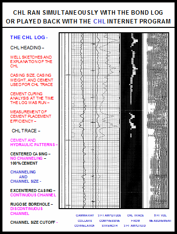

The CHL TRACE AND the CHL HEADING for -
* Assist and add confidence in the initial zone isolation determination
* Measure the cement curing and cement compressive strength at the time of the log
* Indicate cement placement flow pattern and measure the cement placement efficiency
* Indicate channel size and channel size cutoff, plus insight into channeling continuity
* Record the hole size and the cement top relationships
* Provide a heading insert to document the intervals of critical isolation
* Document and help analyze squeeze job results
* Document in one place the well data and cementing data
* Help with cementing field studies for the next well in the area
* Add cement compressive strength to frack vs. production studies
* Initiate channel flow analysis on wells with questionable production
* Note - The CHL server is supported by standby power for 24/7 availability.
The importance of having the knowledge and understanding of In Place Cement Curing, most of the time, is not a Critical Concern, but Knowing that sometimes it is, changes everything.
Having someone in the Well Planning and Approval meeting that routinely evaluates measured In Place Cement Curing and knows and understands that complex Cement Recipes are unique and Cement Curing time needs to be addressed.
AN OPPORTUNITY FOR A LONG TIME PROFESSIONAL RELATIONSHIP
The First Well Drilled in the Area, as shown, the Cementing and Zone Isolation is questionable. To be able to be part of the Improvement Features discussion for the next Well in this area - Communication, as shown.
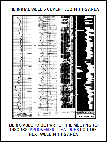
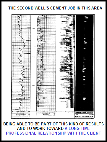
The CHL Trace presentation and the CHL Heading’s goal is to give insight into the Present Cement Job and Zone Isolation on this Well with a look toward the Next Well in this Area.
THE RESULTS OF HAVING THE CHL
for the Before and After Job Sales Calls, using the CHL Heading Data and the addition of the CHL Trace to establish a Long Time Professional Relationship with the Client.
Before the job, having the Vocabulary for Communication for Well Sketch Details and Cementing Data, with DRILLING, who Plans and Designs the Drilling of the Well, and Plans and Designs the Cement Job.
After logging, the Knowledge and the Understanding of the Cement Placement and In Place Cement Curing for the Well, and the confidence to be part of the meeting to discuss Improvement Features for the next Well in this area is a great opportunity for Drilling and Logging to work toward a Long Time Professional Relationship.
The benefit for Drilling, who Plans and Designs the Drilling of the Well, and Plans and Designs the Cement Job, to have the added insight from the Logging Company - Cement Placement and Measured In Place Cement Curing.
From August 1991, to June 2004, 405 CHL Logs were run for 94 Clients for a Wireline Company with twelve Districts and four Sales Offices. For the Salesman that took advantage of the CHL Heading and the addition of the CHL Trace to help develop a Long Time Professional Relationship with his Client, coupled with Reasonable Service, and Competitive Pricing, the long time Jobs and Revenue results are as follows -
Client No. 1 57 CHL Logs plus the New Well Completion
Client No. 2 44 CHL Logs plus the New Well Completion
Client No. 3 35 CHL Logs plus the New Well Completion
Client No. 4 25 CHL Logs plus the New Well Completion
Client No. 5 19 CHL Logs plus the New Well Completion
Client No. 6 15 CHL Logs plus the New Well Completion
Client No. 7 15 CHL Logs plus the New Well Completion
Client No. 8 14 CHL Logs plus the New Well Completion
Client No. 9 12 CHL Logs plus the New Well Completion
Client No. 10 12 CHL Logs plus the New Well Completion
Client No. 11 10 CHL Logs plus the New Well Completion
Client No. 12 9 CHL Logs plus the New Well Completion
Client No. 13 9 CHL Logs plus the New Well Completion
Client No. 14 6 CHL Logs plus the New Well Completion
Client No. 15 6 CHL Logs plus the New Well Completion
Because of this Professional Relationship, the Salesman also was part of the planning for the Client’s Workover Cased Hole Wireline work, which was additional Jobs and Revenue. If the CHL Trace and CHL Heading are not part of the Cement Evaluation Package available to you insist that they be added to your current Cement Evaluation Package.
Drilling, who Plans and Designs the Drilling of the Well, and Plans and Designs the Cement Job, should have the added insight from the Logging Company - Cement Placement and Measured In Place Cement Curing.
Someone in the Well Planning and Approval meeting that routinely evaluates measured In Place Cement Curing and knows and understands that complex Cement Recipe are unique and Cement Curing time needs to addressed.
The CHL - CHL Trace and CHL Heading needs to be part of the available Logging Cement Evaluation Package to make the above possible.
WHAT NEEDS TO BE DONE FOR A CEMENT EVALUATION EDUCATIONAL AND CONFIDENCE BUILDING SOFTWARE PACKAGE AND THE CEMENT EVALUATION TWO PART PACKAGE TO AGAIN BE AVAILABLE -
Part One - Programming is Needed -
The CHL Trace and CHL Heading at the Well Sight -
To again make the CHL Trace and CHL Heading available at the Well Sight, Wheelis Engineering is in search of another Company that provides Electric Wireline Unit Operational Software for Acoustic Cement Bond Logs to discuss an add-on module adapting the existing CHL Trace software and the CHL Heading software to run simultaneously with the Acoustic Cement Bond Log at the Well Sight for the Up or Down Cement Evaluation Meeting. Contact Bill Wheelis at wwheelis@cox.net
To: Your Cased Hole Electric Wireline Provider
cc: wwheelis@cox.net
Subject: The CHL Trace and CHL Heading at the Well Sight
Dear Sir,
Please consider making available the CHL Cement Evaluation Educational and Confidence Building Software Package for the CHL Trace and CHL Heading as an Auxiliary Interpretation Package to the Black Warrior Electric Wireline Unit Operational Software for Acoustic Cement Bond Logs to run the CHL Trace and CHL Heading simultaneously with the Log at the Well Sight.
Sincerely,
Part Two - Programming is Complete -
Before and After the Cement Job at the Clients Office -
The programming is completed for the Before and After Job Communication - the Internet Playback CHL at www.addchl.com
AN EDITORIAL ABOUT THE OFFSHORE BLOWOUT
The last Trial is over – February 2016. The Blowout was a Tragic, High Profile Event that gave the People of the Movement that were in Power the opportunity to further their agenda to destroy the Oil Industry. Attacking the Oil Industry’s Public Image and initialing a huge financial attack on BP from all sides.
The second opportunity the Blowout gave the People of the Movement that are in Power is to impose harsh, complex, impractical, expensive operational regulations under the pretense of preventing any future accidents.
Everyone in the Oil Industry works hard to prevent any kind of Accident. A Blowout destroys the Revenue Potential of the Well. The Oil Industry has over the years developed a practical Well Control System with back ups for every part of the Control System that every Rig and everyone in the Oil Industry uses, test, and works with. People operate these systems, and mistakes are made. This doesn’t mean the system developed from the experience of millions of Wells drilled was bad and needs to be made super complex with all kind of new impractical regulations that the People of the Movement in power can implement to increase the expense and difficult to Drill Future Wells.
All the conveniences, that we enjoy today, are in some way associated with Fossil Fuels, and I guess that pisses the People of the Movement off. But, toxic run off from the high, large garage dump close to every City and Town, or a sewerage system in every City and Town that leaks hundreds of gallows of toxic sewerage every day, exposing pollution to the surface ground water, and every City's and Town's water supply and every homes water supply doesn’t seem to bother the People of the Movement at all, but a few gallons of Fossil Fuel in a million gallon system makes them ballistic and demand, the Oil Companies be punished.
How do you see this?
the CHL TRACE ... a visual, simple, consistent cement evaluation

GAMMA RAY 3 FT AMPLITUDE CHL TRACE 5 FT VDL
OIL WELL CEMENT EVALUATION AND THE DEEPWATER OFFSHORE BLOWOUT
AN EDITORIAL -
The importance of having the knowledge and understanding of Measured In Place Cement Curing, most of the time, is not a critical concern, but knowing that sometimes it is, changes everything.
Cement Curing did not need to be a concern -
In the Gulf, all the previously completed Deepwater Wells were Liner completions thru the Production Zone, which then required long tie back strings from the top of the Liner to the Subsea Well Head. The In Place Cement Curing Time for the Liner's Complex Cementing Recipe for the hundreds of feet of high pressure, high perm, high temperature Production Zone, with the 18 #/gal drilling mud in place, was for 78 to 96 hours before the Complex Cementing Recipe was ask to control the differential pressure from reducing the mud weight from 18 #/gal to 12.5 #/gal completion fluid and In Place Cement Curing was not a concern.
Cement Curing did need to be a concern -
On the Deepwater Blowout Well, the Production Casing String Design was changed to a Superior Casing String Design, a Continuous 9 5/8" to 7" Production String from the well's TD to the Subsea Well Head covering all the Well’s Liner overlaps with a continuous string of casing. The Casing Design made for a more complex cement job. The wiper plug system changed from a two stage system to a three stage system. The Cement Pumping Operation was more complex with the increased volume of the 9 5/8" casing string interval.
First the Cement Slurry was mixed and pumped separated by a multi stage wiper plug system, followed by the mud pumped thru the Drill Pipe to the Well Head, the long 9 5/8" String, and the 7" Casing to the 7" Float Collar to complete the Production Zone Cement Job.
Immediately after Cement Placement, while the Cement Slurry is curing, with any change in the Well's Hydrostatic Balance, the area of critical concern would be the integrity of the Guide Shoe check valve system with the high volume pumped, any slight over displacement would apply force on the Cement Wiper Plug Assembly that could damage the back flow check valve in the 7” Guide Shoe, which would be very hard to detect, leaving the bottom of the casing vulnerable to back flow until the Cement Slurry has had time to cure.
With this Casing Design and not adjusting the Completion Procedure, the In Place Cement Curing Time for the Complex Cementing Recipe for the hundreds of feet of high pressure, high perm, high temperature Production Zone , with 18 #/gal drilling mud in place, was for only 10 to 12 hours before the Complex Cementing Recipe was ask to control the differential pressure from reducing the mud weight from 18 #/gal to 12.5 #/gal completion fluid and In Place Cement Curing was very much a concern.
Cement Evaluation has been made very Complex, Controversial, and Political.
The Cement Evaluation Log reflects the quality of the Well Drilled and Cemented and is a direct reflection on the Drilling Department, which makes the Cement Evaluation Logging very Political and Controversial and led to more Complex Cement Evaluation Presentations, that everyone in the room needs extensive training to understand.
The Industry has not insisted that the Cementing Companies and the Logging Companies make the existing Cement Evaluation Packages Technology present and evaluate Cement Placement and Measured In Place Cement Curing as a critical part of the Cement Evaluation Package process to insure that Drilling has this Knowledge and Understanding for the Well's Completion Planning.
With the the Knowledge and Understanding of Cement Placement and Measured In Place Cement Curing for the Complex Cement Recipes necessary for the Deepwater Wells completed with the 7” Liners thru the high pressure, high perm, high temperature Production Zone on all the previous Deepwater Wells, Drilling's completion plan for the Deepwater Blowout Well's would have insured that In Place Cement Curing would be a concern and be a part of the planning to be sure the well was truly secure before the 18 #/Gal drilling mud was started to be changed out with 12.5 #/gal completion fluid.
For a Offshore Deepwater Well, changing from a 7” Liner Completion with a 9 5/8” to 7” Tie Back String to a superior Casing String Design a Continuous 9 5/8” to 7” Production String
In the Final Approval Meetings for changing the Casing String Design, for an improved Continuous Casing String of 9 5/8” and 7” for the Well’s Production String, was In Place Cement Curing Discussed for the Complex Cementing Recipe for the hundreds of feet of high perm, high temperature, geo-pressured Production Zone?
Drilling needs someone in the meeting to approve the continuous 9 5/8” and 7” Casing Design for the Deepwater Blowout Well that routinely evaluates measured In Place Cement Curing and knows and understands that a complex 18 #/gal Cement Recipe needed for the hundreds of feet of high perm, high temperature, geo-pressured Production Zone will not have developed enough compressive strength in 10 to 12 hours to control reducing the Well’s mud weight from 18.0 #/gal to 12.5 #/gal.

Cement Curing did not need to be a concern -
In all the other previously completed wells, the 7” liner complex cementing recipe was in place 78 to 96 hours before ask to control the differential pressure from reducing the mud weight from 18 #/gal to 12.5 #/gal completion fluid. On all the previous completed wells after cementing the 7” liner thru the production zone, the rig operations to complete the well, created the in place cement curing time that was required and the importance of in place cement curing for the complex production zone cement recipe was lost –
Rig Operations with 18.0 #/gal in the Well -
* Set the liner hanger and clean up the cement job at the liner top and come out of the well from 17,000 ft – 10 to 12 hours
* Trip into the well to 17,000 ft to check and dress the 7” liner top preparing for the tie back casing tie in and trip back out from 17,000 ft – 20 to 24 hours
* Run the cement evaluation log after 30 to 36 hours of cement curing time – 8 to 10 hours
* Rig up and run the 11,500 foot 9 5/8” and 7” tie back casing string to the top of the 7” liner at 17,000 ft and tie into the 7" liner top - 36 to 40 hours
* Hang off the 9 5/8” casing in the well head casing spool and come out of the well from 5,500 ft – 4 to 6 hours
Cement Curing time with 18 #/gal in the well - 78 to 96 hours
Again, the complex cement recipe for the 7” liner production zone on the previous wells had 78 to 96 hours of in place cement curing time with 18 #/gal mud in the well, created by rig operations to complete the well, allowing the cement to cure enough to control the differential pressure from reducing the mud weight from 18 #/gal to 12.5 #/gal completion fluid.
Cement Curing did need to be a concern -
With the improved production casing design, all those rig operations were eliminated, and the production zone’s cement job in place cement curing time with 18#/gal mud in the well was greatly reduced.
Rig Operations with 18.0 #/gal in the Well -
* Hang Off the 9 5/8" Casing for a positive seal in the Subsea Well Head Spool @ 5,230 ft. - 2 to 3 hours
* Come out of the Hole with the 9 5/8" Casing running tool from 5,230 ft. - 3 to 4 hours
* Rig up and start back in the Hole with the Drill Pipe to start chancing out 18.0 #/gal Mud with 12.5 #/gal Completion Fluid - 5 hours
Cement Curing time with 18 #/gal in the well - 10 to 12 hours
Without the knowledge and understanding of cement placement and in place cement curing for the complex cement recipe for the 7” liner production zone on the previous wells, Drilling and everyone must have assumed, that when the casing was run, the cement job was complete, and the cement was set, and the well was secure.
Apparently because of this sinse of security, the change out of the 18 #/gal drilling mud to the 12.5 #/gal completion fluid was started, with the production zone’s cement job in place cement curing time with 18#/gal mud in the well of 10 to 12 hours, without the rig being on high alert, and without a rehearsed well security testing procedure in place. What was the pumping time for the cement recipe used?
Who made the decision to send the Schlumberger Crew in while the continuous casing string of 9 5/8” and 7” for the well’s production string was being run the day before the blowout? The Schlumberger Crew had been called out to run a cement evaluation log thru the 7” production zone. Was it the recommendation and input of the Schlumberger Engineer at the Rig, because he knew to attempt to run a cement evaluation log over the complex 18 lb/gal cementing recipe for the hundreds of feet of high perm, high temperature, geo-pressured 7” production zone with only 10 to 12 hours of in place cement curing, the cement could not have developed enough cement compressive strength for the cement evaluation log to correctly evaluate in place cement curing and zone isolation thru the critical zone interval for the well’s 7” production zone, and logging 18 lb/gal green cement would be a waste of time?
With the knowledge and understanding of cement placement and in place cement curing for the complex cement recipe for the 7” liner production zone on the previous wells, Drilling has lots of options to change out the mud and secure the well using the better casing design, the continuous casing string of 9 5/8” and 7” for the well’s production string.
Not using the knowledge and understanding of cement placement and in place cement curing for the complex cement recipe for the 7” liner production zone on the previous wells, and planning for sufficient in place cement curing time, was much more significant, than only running 6 of the proposed 22 casing centerlizers.
the CHL TRACE ... a visual, simple, consistent cement evaluation

GAMMA RAY 3 FT AMPLITUDE CHL TRACE 5 FT VDL
CHL - CEMENT HYDRAULICS LOG -
A PROVEN, VISUAL, SIMPLE, STRAIGHT FORWARD INTERPRETATION,
USING THE 3 FT AMPLITUDE SIGNAL, ADDITION FOR THE BOND LOG AND
THE BOND LOG HEADING TO HAVE CEMENT PLACEMENT AND MEASURED IN
PLACE CEMENT CURING AT THE TIME THE BOND LOG WAS RUN FOR
THE INITIAL UP OR DOWN ZONE ISOLATION MEETING, PLUS DETAILED
AFTER JOB ANALYSIS FOR THE DESIGNER OF THE CEMENT JOB.
A CEMENT EVALUATION LOG EVERYONE IN THE ROOM CAN UNDERSTAND.
THE CHL LOG IS A PROVEN PRODUCT WITH OVER FOUR HUNDRED LOGS RUN FOR OVER NINETY DIFFERENT PRODUCTION COMPANIES.


AN EDITORIAL -
RESPONSE TO THE QUESTION –
In the approval meetings for changing the casing string design, for an improved final continuous casing string of 9 5/8” and 7” for the well’s production string, was in place cement curing discussed for the complex cementing recipe for the hundreds of feet of high perm, high temperature, geo-pressured production zone?
ANSWER – NO
In all my years working in the Oil Industry and being a part of casing design approval meetings, in place cement curing has never been part of the approval agenda. Even the Industry Experts at the previous trial did not indicate in place cement curing to be a concern.
Had we been aware that in place cement curing for the complex cementing recipe necessary for the hundreds of feet of high perm, high temperature, geo-pressure production zone would require 30 to 36 hours to start generating enough cement compressive strength to start controlling the production zone, the completion procedure for securing the well would have been different.
Such as, the top of the continuous 9 5/8” and 7” production casing string would be hung off in the 9 5/8” casing spool in the well head and secured and tested which is a part of the well head structure, a traditional industry standard. The well’s annular area and casing back side with 18 #/gal drilling mud and cement would be secure from up flow. To secure the bottom of the production string guide shoe and float collar, with the well secure with 18 #/gal drilling mud still in the well, go in the well with a 7” squeeze retainer to check the security of the guide shoe and float collar plus set the cement retainer just above the 7" float collar for additional well security from in flow at the well’s TD from the production zone.
Then, with the top of the continuous 9 5/8” and 7” production casing string securely hung off in the well head and the bottom of the production casing string guide shoe and float collar secured with the addition of a 7” cement retainer set just above the 7" float collar, the casing string should be secure. With the rig on high alert, and with a rehearsed well security testing procedure, change out the 18 #/gal drilling mud with the 12.5 #/gal completion fluid and finish completing the well.
QUESTION -
Why were you not aware of the importance of in place cement curing for the production zone complex cementing recipe necessary for the hundreds of feet of high perm, high temperature, geo-pressure production zone?
ANSWER –
The importance of in place cement curing for this complex cementing recipe on all the previous deep water wells, which were 7” liner production strings, was lost because of all the necessary well completion procedures following cementing the liner which gave the impression that in place cement curing was not a concern, such as -
* Set the liner hanger and clean up the cement job at the liner top and come out of the well from 17,000 ft –
* Trip into the well to 17,000 ft to check and dress the 7” liner top preparing for the tie back casing tie in and trip back out from 17,000 ft
* Run the cement evaluation log after 30 to 36 hours of cement curing time * Rig up and run the 11,500 foot 9 5/8” and 7” tie back casing string to the top of the 7” liner at 17,000 ft and tie into the 7" liner top
* Hang off the 9 5/8” casing in the well head casing spool and come out of the well from 5,500 ft
This gave the cement 78 to 96 hours of curing time with 18 #/gal drilling mud before the cement was ask to control the production zone differential pressure from reducing the mud weight from 18 #/gal to 12.5 #/gal completion fluid.
Again, on all the previous completed wells, after cementing the 7” liner thru the production zone, the rig operations necessary to finish completing the well, created the in place cement curing time that was required for well security and in place cement curing concerns was not an issue.
QUESTION -
What would be your recommendation of all future deep water completions?
ANSWER –
The continuous 9 5/8” and 7” production casing string is a good casing design for continuous pipe from the well head to the well’s TD, top to bottom, covering all the liner sections needed to drill the well to these depths to insure casing integrity for these complex, high production rate very expensive wells.
But the awareness of cement placement and in place cement curing for the complex cementing recipe necessary for the hundreds of feet of high perm, high temperature, geo-pressure production zones, needs to be an integral part of the planning for the safe completion of the future wells.
AS A SOLUTION -
The industry needs to be aware of and have available cement placement analysis and measured in place cement curing as part of the industry’s cement evaluation package. The CHL is existing interpretation technology with a visual, simple, consistent presentation with the CHL Trace for cement zone isolation evaluation and cement placement analysis and the CHL Heading having measured in place cement curing in an easy to understand format.
The exiting cement evaluation technology evaluates what happens before and after cement placement, but none of the existing cement evaluation Logging packages technology presents and evaluates and measures the in place cement curing process. This technology has not been routinely a part of the available cement evaluation Logging package for the industry, even though it is a critical part of the cement evaluation process to insure the success of the cement job.
The addition of cement placement analysis and measured in place cement curing as a routine part of the of the cement evaluation Logging package in a proven, visual, simple, consistent log interpretation presentation so everyone in the room can comfortably understand - cement zone isolation evaluation and cement placement analysis and measured in place cement curing - would insure that in place cement curing would be a concern and a part of the completion planning.
QUESTION -
IS THIS REASONABLE ANSWERS TO THE QUESTIONS?
AN EDITORIAL -
The Cementing Companies main focus is to help design and laboratory test each cement recipes, sell cement and the necessary designed additives for the unique cementing recipe designed for each well, furnish the personnel and the specialized equipment to deliver and mix and pump the cement job at the well sight and does not include in place cement curing analysis.
The Logging Companies cement evaluation package main focus, as directed by the industry, is toward the up or down cement evaluation meeting immediately after running the well’s cement evaluation log to determine, with the rig waiting, if the cement job is satisfactory or unsatisfactory for zone isolation thru the critical intervals for the well’s production zones which determines the sequence of the rest of the completion steps to continue finishing the completion of the well. This focus does not normally include measured in place cement curing analysis.
The importance of having the knowledge and understanding of in place cement curing, most of the time, is not a critical concern, but knowing that sometimes it is, changes everything.
If the CHL - CHL Trace and CHL Trace, had been available and used on the previous 7" Liner wells, maybe different questions would have been asked and the Blowout would have been avoided.
WHAT HAS TO BE DONE FOR THE CHL - CHL TRACE AND CHL HEADING TO BE MADE AVAILABLE AS PART OF THE CURRENT CEMENT EVALUATION PACKAGES.
Part One
The CHL Trace and CHL Heading at the Well Sight -
To again make the CHL Trace and CHL Heading available at the Well Sight, Wheelis Engineering is in search of another Company that provides Electric Wireline Unit Operational Software for Acoustic Cement Bond Logs to discuss entering into a software licensing agreement, adapting the existing CHL Trace software and the CHL Heading software to run simultaneously with the Acoustic Cement Bond Log at the Well Sight for the Up or Down Cement Evaluation Meeting. Contact Bill Wheelis at wwheelis@cox.net
The programming is needed for the Well Sight CHL Trace and CHL Heading to run the CHL simultaneously with the Bond Log at the Well Sight.
Part Two
Before and After the Cement Job at the Clients Office -
The programming is completed for Before and After Job Communication - the Internet CHL at www.addchl.com
PROGRAMMING TO Add the CHL -
the CHL TRACE ... a visual, simple, consistent cement evaluation

GAMMA RAY 3 FT AMPLITUDE CHL TRACE 5 FT VDL
A CEMENT EVALUATION LOG EVERYONE IN THE ROOM CAN UNDERSTAND, WHEN THE WELL'S CRITICAL INTERVALS FOR ZONE ISOLATION ARE NOT LOGGED SHOWING 100% CURED CEMENT.
For the CHL Trace and CHL Heading at the Well Sight -
To again make the CHL Trace and CHL Heading available at the Well Sight, Wheelis Engineering is in search of another Company that provides Electric Wireline Unit Operational Software for Acoustic Cement Bond Logs to adapt the existing CHL Trace software and the CHL Heading software to run simultaneously with the Acoustic Cement Bond Log at the Well Sight for the Up or Down Cement Evaluation Meeting. Contact Bill Wheelis at wwheelis@cox.net
CHL - Cement Hydraulics Log is a proven, visual, simple, straight forward Cement Evaluation interpretation, using the 3 ft amplitude signal. The CHL identifies the 100% Cement Reading for your casing size, casing thickness, and cement compressive strength and couples it with the interpretation cutoff limit for possible 100% solids, Crystalline Cement, for a consistent interpretation in a twenty line display with shading from Black to Grey to White.
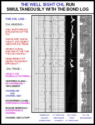

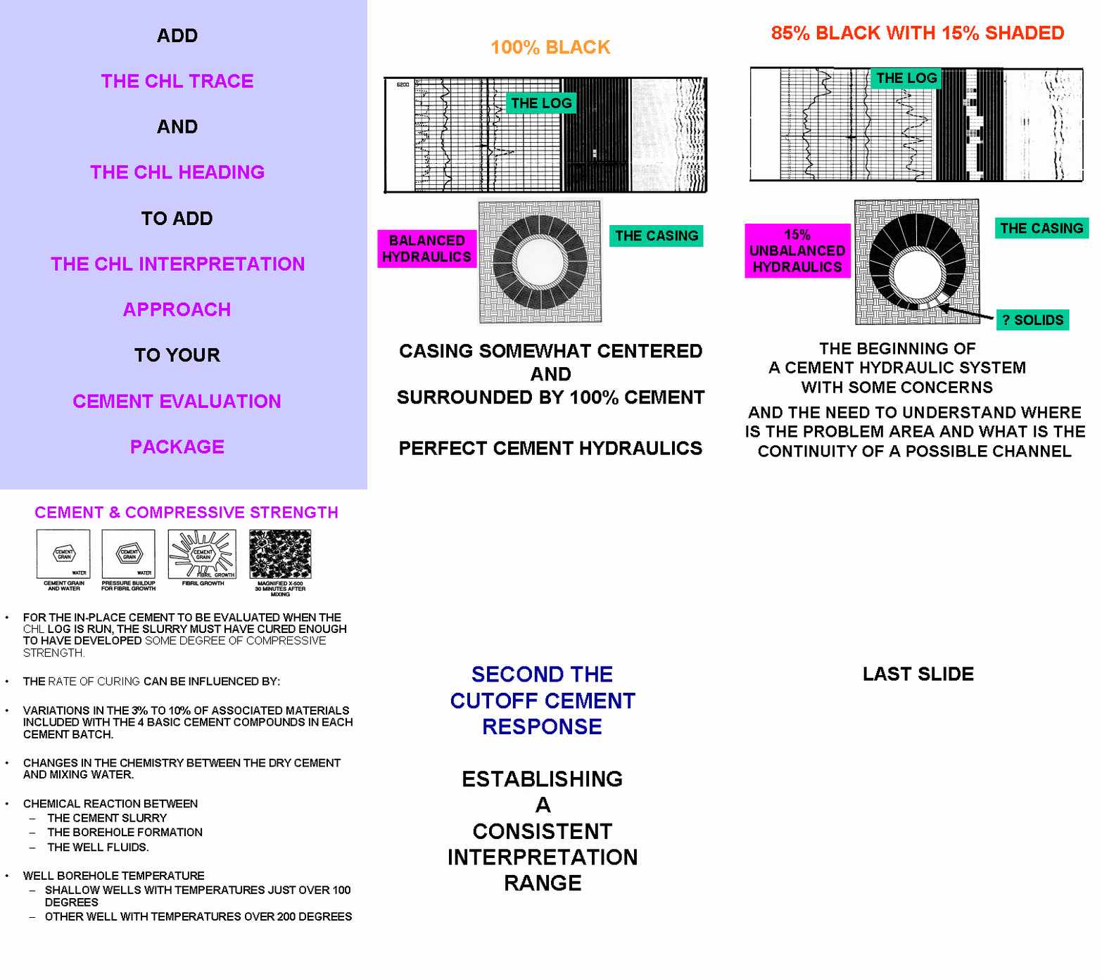
The overall CHL display is also designed to give insight into the cement’s job displacement pattern -
1. Is the casing center with uniform displacement,
2. Is the casing excentered with uniform displacement on the high side,
3. Is the cementing column rotating and spiraling up the hole?

If there is a Question with the Cement Job thru the critical intervals for the Well’s Production Zones, does the Channel have continuity to a Zone of unwanted permeability? Is there a continuous 4 LINE WHITE CHANNEL, or larger, to a Zone of Pereability in the critical intervals?
Cement Placement Analysis and Measured In Place Cement Curing at the time the Bond Log was run –


At the Well Sight with the Rig waiting for a decision, the main focus for the Cement Evaluation Package is toward the Up or Down Cement Evaluation Meeting immediately after running the Well’s Cement Evaluation Log. The CHL Presentation gives the Logging Engineer at the Well Sight and the Company Pusher on the Rig and the Decision Makers at the Up or Down Meeting, a visual, simple, consistent cement evaluation, that everyone can understand, as to whether the Cement Job is Satisfactory or Unsatisfactory for Zone Isolation thru the Critical Intervals for the Well’s Production Zones. A decision made with confidence.
A quick decision reduces the Rig Standby Time and the Well’s Completion sequence can continue quickly.
A CEMENT EVALUATION LOG EVERYONE IN THE ROOM CAN UNDERSTAND, WHEN THE WELL'S CRITICAL INTERVALS FOR ZONE ISOLATION ARE NOT LOGGED SHOWING 100% CURED CEMENT.


The CHL presentation and the heading’s goal is to give insight into the present cement job and zone isolation on this well with a look toward the next well in this area.
the CHL TRACE ... a visual, simple, consistent cement evaluation

GAMMA RAY 3 FT AMPLITUDE CHL TRACE 5 FT VDL
TYPICAL CHL PROGRAMMING SCREENS -
The CHL Heading and CHL Trace for the Initial CHL at the Well
Sight


For the CHL Trace and CHL Heading at the Well Sight -
To again make the CHL Trace and CHL Heading available at the Well Sight, Wheelis Engineering is in search of another Company that provides Electric Wireline Unit Operational Software for Acoustic Cement Bond Logs to discuss an add-on module adapting the existing CHL Trace software and the CHL Heading software to run simultaneously with the Acoustic Cement Bond Log at the Well Sight for the Up or Down Cement Evaluation Meeting. Contact Bill Wheelis at wwheelis@cox.net
To: Your Cased Hole Electric Wireline Provider
cc; wwheelis@cox.net
Subject: The CHL Trace and CHL Heading at the Well Sight
Dear Sir,
Please consider making available the CHL Cement Evaluation Educational and Confidence Building Software Package for the CHL Trace and CHL Heading as an Auxiliary Interpretation Package to the Black Warrior Electric Wireline Unit Operational Software for Acoustic Cement Bond Logs to run the CHL Trace and CHL Heading simultaneously with the Log at the Well Sight.
Sincerely,
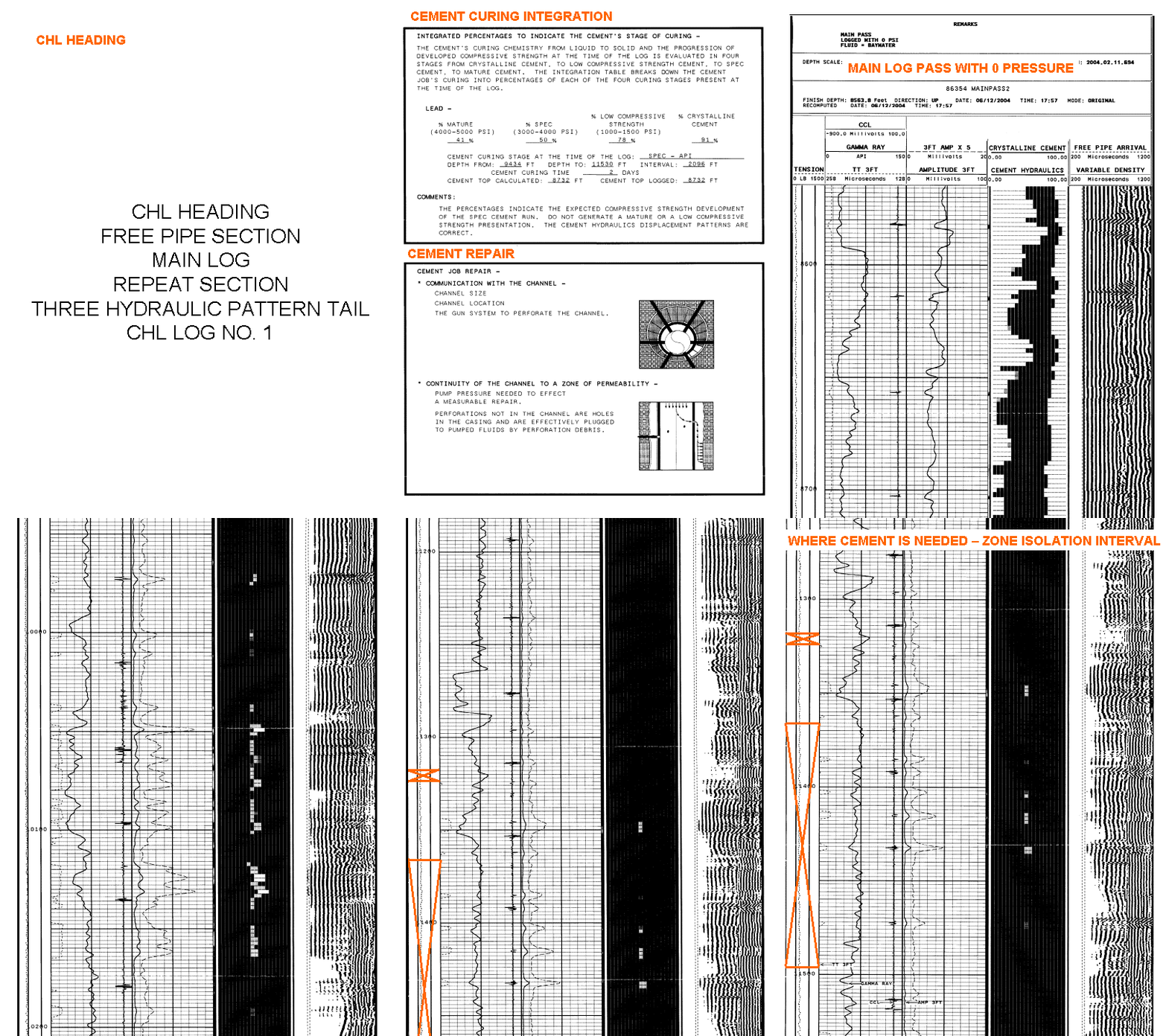
CHL LOG EXAMPLES AND POWER POINTS PRESENTATIONS -
the CHL TRACE ... a visual, simple, consistent cement evaluation

GAMMA RAY 3 FT AMPLITUDE CHL TRACE 5 FT VDL
THE CHL LOG - > |
|
|
|
|
|
|
ANY QUESTIONS ABOUT THE CHL INTERPRETATION APPROACH, AND THE CHL INTERNET PROGRAM CONTACT BILL WHEELIS AT WHEELIS ENGINEERING, LTD, PHONE NUMBER 1 – 504 – 393 –0263 OR E-MAIL wwheelis@cox.net.
THE CHL LOG IS A PROVEN PRODUCT WITH OVER FOUR HUNDRED LOGS RUN FOR OVER NINETY DIFFERENT PRODUCTION COMPANIES.
THE CHL WILL BE AN ASSET TO SERVICE COMPANIES BY -
1. ASSISTING AND ADDING CONFIDENCE IN THE INITIAL ZONE ISOLATION DETERMINATION FOR EACH WELL.
2. THE CHL LOG AND PROGRAM IS A TRAINING AND TEACHING AID FOR BETTER UNDERSTANDING OF OIL WELL CEMENTING FOR A BETTER CEMENT EVALUATION INTERPRETATION.
3. THE TRAINING AND TEACHING CAN BE REVIEWED THRU THE CHL WEBSITE SCREENS AND THE ABOVE POWER POINT PRESENTATIONS.
4. THE CHL PROGRAM HAS THE POTENTIAL TO HELP CREATE DIALOGUE BETWEEN PARTIES FOR COMMUNICATION TO HELP ESTABLISH A RELATIONSHIPS FOR SUCCESS FOR BOTH THE PRODUCTION COMPANY AND WIRELINE SALES WITH BETTER CEMENTING JOBS ON FUTURE WELLS.
5. HELP EACH SERVICE COMPANY’S GOAL TO INCREASE MARKET SHARE AND CASED HOLE REVENUE IN THE NEW WELL COMPLETION MARKET.
FOR THE CEMENT JOB DESIGNER -
AND THE PRODUCTION COMPANIES DOING CEMENT EVALUATION FIELD STUDIES BEFORE THE NEXT NEW WELL COMPLETION, THE CHL OFFERS -
1. ASSISTING AND ADDING CONFIDENCE IN THE INITIAL ZONE ISOLATION DETERMINATION FOR EACH WELL.
2. THE CHL MEASURES AND DOCUMENTS THE CEMENTING RECIPE’S CURING PERCENTAGES AT THE TIME OF THE LOG.
3. THE CHL CONSISTENTLY MEASURES THE CEMENT DISPLACEMENT EFFICIENCY PERCENTAGE.
4. THE PROGRAM OUTLINES THE RELATIONSHIP BETWEEN THE CEMENT TOPS AND THE HOLE SIZE.
5. THE CHL ISOLATION ZONE SECTION DOCUMENTS THE CRITICAL INTERVALS OF INTEREST.
6. IF THERE WAS A SQUEEZE JOB, THE CHL SQUEEZE ANALYSIS SECTION DOCUMENTS THE CEMENT REPAIR EVALUATION.
7. THE CHL HEADING DOCUMENTS THE CEMENT JOB.
THE CHL HELPS ORGANIZE THE CRITICAL AREAS OF CONCERNS FOR THE FIELD STUDY TO HELP PLAN THE NEXT NEW WELL COMPLETION.
CEMENTING JOB AND RECIPE EVALUATION -
DID THE PLANNED CEMENT JOB, WITH THE SELECTED CEMENTING RECIPE, PERFORM AS DESIGNED AND INTENDED WHEN PUMPED UNDER THE PLACEMENT HYDRAULICS CONDITIONS FOR CEMENT PLACEMENT? DID THE IN PLACE CEMENT SLURRY CURE AS DESIGNED IN THE ENVIRONMENT OF THIS WELL AND THIS AREA?
THE CHL INTERPRETATION APPROACH INCLUDES IDENTIFICATION OF THE THREE HYDRAULIC PLACEMENT PATTERNS AND THE MEASURE OF DISPLACEMENT EFFICIENCY TO PROVIDE UNDERSTANDING OF THE HYDRAULICS OF THE CEMENT JOB.
FOR MEASURED IN PLACE CEMENT CURING, THE CHL MEASURES A CURING COMPRESSIVE STRENGTH ANALYSIS AT THE TIME THE LOG WAS RUN ACCORDING TO THE WELL’S CASING SIZE, CASING WEIGHT, AND CEMENT WEIGHT.
THE CHL FOR UNDERSTANDING AND KNOWLEDGE FOR THE CEMENTING RECIPE’S PERFORMANCE IN THE WELL CONDITIONS AND ENVIRONMENT OF THIS WELL AND WELLS IN THIS AREA TO REVIEW CEMENT, CEMENT SLURRIES, CEMENT PLACEMENT HYDRAULICS, AND IN PLACE CEMENT CURING, OPEN THE CEMENT CURING POWER POINT PRESENTATION –
THE CEMENT CURING POWER POINT PRESENTATION
THE OBJECTIVE OF THE CHL IS TO ASSIST THE CEMENT JOB DESIGNER EVALUATE THE CEMENT JOB DESIGN FOR CEMENT PLACEMENT AND THE CEMENTING RECIPE FOR IN PLACE CEMENT CURING AT THE TIME THE LOG WAS RUN ON THE WELL LOGGED. UNDERSTANDING AND KNOWLEDGE FOR THE CEMENT JOB DESIGN FOR THE NEXT WELL IN THE AREA.


ALSO THE QUESTION OF WELL PRODUCTION -
WHAT RATE SHOULD BE PRODUCING
VS
WHAT RATE IS PRODUCING ANALYSIS
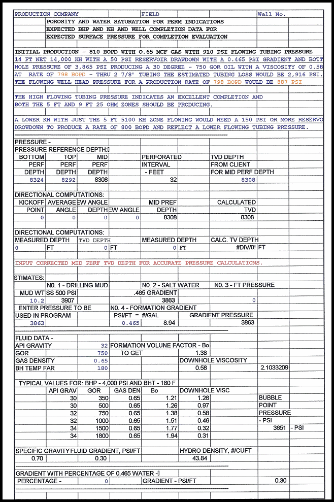
USING POROSITY AND WATER SATURATION FOR PERM INDICATIONS TO GET THE SOUGHT AFTER DOWNHOLE KH VALUE
AN EXCEL SPREADSHEET FOR BOTH OIL WELLS AND GAS WELLS TO ORGANIZE THE PRESENTATION OF THE LOG INDICATED IDEAL DOWNHOLE PRODUCTION RATE CONVERTED TO THE SURFACE RATE AND FLOWING PRESSURE FOR COMPARISON TO THE WELL TEST SURFACE RATE AND FLOWING WELL HEAD PRESSURE
* COMPLETION INTERVAL DEPTHS
* BOTTOM HOLE PRESSURE SELECTION
* FLUID DATA AND FLUID PARAMETERS
* POROSITY AND WATER SATURATION FOR PERM INDICATIONS
* KH AND KH FLOWING PROFILE
* RESERVOIR PRODUCTION RATE FOR SELECTED RESERVOIR DRAWDOWN USING DARCY, VOGEL – DARCY, AND JONES IPR
* MATCHING THE RESERVOIR DOWNHOLE RATE WITH THE WELL’S COMPLETION HARDWARE USING NODAL ANALYSIS FOR THE MATCHING SURFACE RATE AND FLOWING PRESSURE
EXAMPLE OF THE EXCEL SPREADSHEET FOR AN OIL WELL –
QUESTION FOR THIS OIL WELL WITH TWO HIGH PERM LENSES,
ARE BOTH LENSES FLOWING AT INITIAL PRODUCTION?


FOR A COPY OF THE EXCEL SPREADSHEET ONE FOR OIL WELLS AND ONE FOR GAS WELLS E-MAIL wwheelis@cox.net. THE TWO EXCEL FILES WILL BE ATTACHED TO THE REPLY.
OIL FIELD CONSULTING SERVICES -
WHEELIS ENGINEERING, LTD
609 ADEE LANE
GRETNA, LOUISIANA 70056
FIELD STUDY OR LEASE EVALUATION HELP –
OPEN HOLE LOGS ANALYSIS
CEMENT AND ZONE ISOLATION ANALYSIS FOR
NEW WELL COMPLETION, OR WELL WORKOVER
ILLUSTRATED ON THIS WEBSITE – www.chllogs.com
FIELD STUDY OR LEASE EVALUATION HELP -
LOG KH, FLUID, PRESSURE, AND PRODUCTION ANALYSIS
FOR REVENUE EVALUATION
DONE CONSISTENTLY IN A EXCEL SPREAD SHEETS FORMAT
CONSULTING RATES -
WORKING IN MY OFFICE - $600.00 PER DAY OR $300.00 PER HALF a DAY
WORKING AT YOUR OFFICE - $900.00 PER DAY OR $600.00 PER HALF a DAY
CONTACT -
BILL WHEELIS PHONE – 1 - 504 – 393 – 0263 E-MAIL – wwheelis@cox.net
LOOKING AT WELLS WITH QUESTIONABLE PRODUCTION
---- START YOUR EVALUATION HERE!!!
ON WELLS WITH QUESTIONABLE PRODUCTION, WHAT WOULD BE THE FLUID FLOW MECHANICS
OF A PRODUCING CHANNEL??
1. CHANNEL WIDTH
2. CHANNEL LENGTH AND CONFIGURATION
3. CHANNEL CONTINUITY
4. PRESSURE DIFFERENTIAL AVAILABLE FOR FLOW
5. CHANNEL FLOW RATE
START THE RESEARCH BY REFRESHING THE CEMENT EVALUATION PACKAGE FOR THE WELL USING
THE CHL PROGRAM FOR THE –
1. CHANNEL WIDTH FROM THE CHL
2. CHANNEL LENGTH AND CONFIGURATION FROM THE CHL
3. CHANNEL CONTINUITY FROM THE CHL CEMENT PLACEMENT HYDRAULICS UNDERSTANDING
THEN ADD THE DIFFERENTIAL PRESSURE AND THE FLOW RATE TO ESTABLISH IF THE FLUID
FLOW MECHANICS CONDITIONS ARE SUITABLE FOR CHANNEL FLOW.
E-MAIL THE FOLLOWING TO wwheelis@cox.net
1. THE OPEN HOLE LOG – RESISTIVITY AND POROSITY FOR THE PRODUCTION INTERVAL
2. ZONE’S PRESSURE DATA – INITIAL SHUT IN BOTTOM HOLE PRESSURE,
PRESENT SHUT IN BOTTOM HOLE PRESSURE, PRESENT PRODUCTION
RATE, AND FLOWING BOTTOM HOLE PRESSURE
3. THE MAIN CEMENT EVALUATION LOG FILE IN A PBM OR A PDF FORMAT
4. THE CORRESPONDING LAS DATA FILE FOR THE MAIN CEMENT
EVALUATION LOG WITH THE DEPTH AND THE 3 FT AMPLITUDE VALUES
5. THE WELL SKETCH DATA – CASING SIZE, CASING WEIGHT, AND
CEMENT WEIGHT THRU THE PRODUCTION INTERVAL.
THE CHL TRACE WILL BE INSERTED ON TO THE MAIN CEMENT EVALUATION LOG
FILE WHICH INDICATES CHANNEL SIZE, CHANNEL LENGTH, CHANNEL CONFIGURATION, AND CHANNEL CONTINUITY. THE RESULTS AND
INTERPRETATION WILL BE PROMPTLY RETURNED FOR YOUR DETERMINATION
IF THE EXISTING FLUID FLOW MECHANICS CONDITIONS MAKE IT POSSIBLE FOR
FLUID FLOW THRU A CHANNEL INTO THE PRODUCTION PERFORATIONS.
ADDING THE CHL TRACE AND THE CHL HEADING FOR THE CHL INTERPRETATION APPROACH TO YOUR CEMENT EVALUATION PACKAGE CAN BE EASILY DONE.
THE EASY TO RUN, INTERACTIVE CHL TRACE AND CHL HEADING PROGRAM, IS AVAILABLE AT THE WEBSITE www.addchl.com.
TO REVIEW THE FEATURES OF THE CHL INTERNET PROGRAM AND THE SCREEN SEQUENCE OF THE CHL PROGRAM DISCUSSED ABOVE, CHECK THE REVIEW CHL PROGRAM BUTTON.
THE OPERATING INSTRUCTIONS ARE AS FOLLOWS:
OPERATING INSTRUCTIONS CAN ALWAYS BE IMPROVED. IF WHEN USING THESE
INSTRUCTIONS
SHOULD YOU HAVE ANY SUGGESTED IMPROVEMENTS, PLEASE E-MAIL THE IMPROVEMENTS.
WHEN THEY ARE ADDED TO THE OPERATING INSTRUCTIONS, THEN IN THE FUTURE EVERYONE
CAN TAKE ADVANTAGE OF YOUR SUGGESTED IMPROVEMENTS.
AT THE WELL SIGHT SETUP AND RUN THE CEMENT EVALUATION LOG -
CEMENT TOPS CAN BE IN ONE OF THREE PLACES -
1. IN THE OPEN HOLE INTERVAL
2. IN THE CASING OVERLAP INTERVAL, OR
3. AT THE SURFACE WITH BARRELS OF CEMENT TO SURFACE
IF THE CEMENT DATA IS AVAILABLE AND YOU HAVE TIME AT THE WELL SIGHT, USE THE FIRST FOUR SCREENS OF ONE OF THE JOB STRUCTURE’S PROGRAM TO CALCULATE THE CEMENT TOPS TO HELP ORGANIZE THE LOGGING JOB
AT THE WELL SIGHT TO ADD THE CHL TRACE AND THE CHL HEADING -
SET UP A FOLDER ON YOUR COMPUTER FOR THE WELL TO BE ANALYZED. PLACE THE WELL’S MAIN LOG SECTION PDF FILE OR THE WELL’S MAIN LOG SECTION PBM FILE IN THE FOLDER. THEN, ADD THE LAS FILE FOR THE MAIN LOG SECTION WITH THE WELL DEPTH AND THE 3 FT AMPLITUDE DATA IN THE WELL’S FOLDER.LOG ON TO THE INTERNET AND GO TO www.addchl.com. ENTER YOUR USER NAME AND PASSWORD AND LOG ON TO THE CHL PROGRAM.
PROGRAM NOTE: WHEN LOGGING IN, IF THE PROGRAM DOES NOT MOVE TO THE MAIN CHL PROGRAM SCREEN, CHECK THE POP-UP BLOCKER. SET THE POP-UP BLOCKER TO OPEN - "SITE POP-UP ALLOWED".
AT THE MAIN CHL PROGRAM SCREEN, SELECT –
NO. 1 JOB STRUCTURE
ON THE FIRST JOB STRUCTURE SCREEN AT TYPE OF CASING COMPLETION, SELECT ONE OF THE FOLLOWING:
1. FIRST PASS CHL
2. PRODUCTION CASING CEMENTING
3. LINER CEMENTING
4. PRODUCTION CASING WITH STAGE COLLAR CEMENTING 5. PRODUCTION CASING WITH BRADENHEAD CEMENTING
NOTE: THE JOB STRUCTURE CONTAINS THE SEQUENCE OF CHL SCREENS FOR THE WELL AND CEMENT JOB SELECTED.
FOR JOBS, AT THE WELL SIGHT WITH LIMITED WELL AND CEMENTING DATA AVAILABLE -
AT THE MAIN CHL PROGRAM SCREEN, SELECT –
NO. 1 JOB STRUCTURE
ON THE FIRST JOB STRUCTURE SCREEN AT TYPE OF CASING COMPLETION, SELECT -
1. FIRST PASS CHL
NOTE: THE JOB STRUCTURE - FIRST PASS CHL - REQUIRES MINIMUM WELL DATA AND CEMENT DATA INPUTS.
PROGRAM NOTE: NORMALLY, THE LIS NAME FOR THE 3 FT AMPLITUDE FOR MOST LOGGING TOOLS IS “AM3F” WHICH IS THE DEFAULT FOR THE PROGRAM. IF YOU HAVE ANY PROBLEMS CREATING THE CHL TRACE IN STEP NO. 3 “PROCESS LOG”, CHECK THE LAS FILE IN NOTEPAD FOR THE WELL’S 3 FT AMPLITUDE LIS NAME. ON THE FIRST JOB STRUCTURE SCREEN, VERIFY THE LIS NAME FOR THE 3 FT AMPLITUDE IS INPUT CORRECTLY.
FROM THE JOB TICKET –
PRODUCTION CASING SIZE (INCHES)
WELL DEPTH (FT)
CASING SETTING DEPTH – GUIDE SHOE SET @ (FT)
FLOAT COLLAR – PBTD @ (TD FOR THE LOG) (FT)
(SHOULD BE ONE TO TWO JOINTS ABOVE THE GUIDE SHOE)
SELECTED CASING WEIGHT FOR THE LOG (SELECT CASING WEIGHT AT WELL’S TD (#/FT)
1. SCREEN NO 1 - INPUT WELL DATA –
CASING SIZE
WELL DEPTH
CASING SETTING DEPTH
FLOAT COLLAR – PBTD
LOGGING MUD WEIGHT
CASING WEIGHT - THE WEIGHT AT WELL’S TD
CEMENTING DATA –
NOTE: DETERMINE FROM THE CLIENT, IF THE WELL IS A SINGLE CEMENT JOB, OR ARE A TWO CEMENT JOB.
CEMENT WEIGHT @ WELL’S TD (#/GAL) CEMENT SACKS (SKS) CEMENT VOLUME FACTOR (CUFT/SKS) NOTE: IF NO CEMENTING DATA IS AVAILABLE AT THIS TIME – SELECT THE CEMENT WEIGHT – 16.0 #/GAL
CEMENT WEIGHT INPUT –
IF FURNISHED BY THE CLIENT, INPUT THE CEMENT WEIGHT AT THE WELL'S TD OR SELECT A SUITABLE CEMENT WEIGHT FROM THOSE SUGGESTED ON THE INPUT SCREEN.
CEMENT CURING TIME -
FROM OPEN HOLE TIE IN LOG - MONTH/DAY/YEAR
INPUT ESTIMATED CEMENT TIME IN DAYS
2. SCREEN NO. 2 - WELL DATA
CHECK INPUT DATA
3. SCREEN NO. 3 – LOG CHECK AND QUALITY CONTROL VALUES
TOOL DATA
FLUID DATA
FORMATION DATA
CASING DATA
4. SCREEN NO. 4 - LOG CHECK AND QUALITY CONTROL VALUES
CHECK TOOL VALUES
5. SCREEN NO. 5 – CHL LOGGING PARAMETERS
CHECK VALUES RETURN TO THE MAIN CHL PROGRAM SCREEN
AT THE MAIN CHL PROGRAM SCREEN, SELECT –
NO. 3. PROCESS LOG - TIME REQUIRED 30 TO 90 SECONDS
1. BROWSE TO THE WELL’S FOLDER AND SELECT THE MAIN LOG SECTION LAS FILE.
2. SELECT THE LOGGING COMPANY THAT RAN THE LOG TO SET THE PRE-SET STRETCH FACTOR AND WIDEN FACTOR.
NOTE: THIS IS TO MATCH THE LOG’S DISPLAY DENSITY TO THE CHL’S DISPLAY DENSITY OF 200 PIXELS PER INCH
3. SELECT DESIRED TRACK FORMAT – 3 TRACK OR 4 TRACK 4. CREATE CHL TRACK.
NOTE: THIS CREATES THE CHL TRACE IMAGE TO BE PASTED TO THE MAIN LOG SECTION LATER. THE PROCESS NORMALLY TAKES ABOUT 30 TO 90 SECONDS. THE SCREEN WILL BE FILLED WITH DEPTH NUMBERS AS THE PROCESS RUNS. WHEN THE PROCESS IS COMPLETED, THE PROGRAM RETURNS TO THE MAIN CHL SCREEN.
AT THE MAIN CHL PROGRAM SCREEN, SELECT –
NO. 4. INTEGRATION RESULTS THE INTEGRATION SCREEN SHOULD BE FILLED WITH NUMBERS INDICATING THE LOG SECTION WAS PROPERLY PROCESSED.
1. RETURN TO THE MAIN CHL PROGRAM SCREEN.
PROGRAM NOTE: IN NO. 3. CREATE THE CHL TRACE, IF THE DEPTH NUMBER DID NOT APPEAR AND IN NO. 4 INTEGRATIONS RESULTS SCREEN IS NOT POPULATED, OPEN THE LOG’S LAS FILE IN NOTEPAD AND VERIFY THAT THE LAS NAME FOR THE 3 FT AMPLITUDE ON THE LOG’S LAS FILE AND LAS PROGRAM INPUT JOB STRUCTURE SCREEN ARE THE SAME.
AT THE MAIN CHL PROGRAM SCREEN, SELECT –
NO. 5. PLOT HEADER INSERTS - TIME REQUIRED 30 TO 90 SECONDS
1. BROWSE TO THE WELL’S FOLDER AND SELECT THE MAIN LOG SECTION PDF OR PBM FILE
2. CREATE HEADERS. CHECK THE CHL HEADING DATA INPUTS
3. SUBMIT HEADERS.
NOTE: THIS PROCESS ADDS THE CHL HEADING IMAGES TO THE MAIN LOG SECTION. THE PROCESS NORMALLY TAKES ABOUT 30 TO 90 SECONDS. ON THE LEFT OF THE SCREEN THE HEADING INSERTS WILL APPEAR AS THEY ARE SUBMITTED. WHEN THE PROCESS IS COMPLETED, THE PROGRAM RETURNS TO THE MAIN CHL SCREEN
AT THE MAIN CHL PROGRAM SCREEN, SELECT –
NO. 6. MERGE LOG RESULTS - TIME REQUIRED 30 TO 90 SECONDS TO LOAD SCREEN
NOTE: FOR THE LOG WITH THE CHL HEADING IMAGES AND THE MAIN LOG SECTION TO BE TRANSFERRED TO YOUR COMPUTER, IT WILL TAKE ONE TO TWO MINUTES.
1. FOLLOW THE INSTRUCTIONS ON THE SCREEN AND OVERLAY THE CHL TRACE IMAGE AT THE CORRECT DEPTH, PLUS ADD THE CHL SCALES AT THE TOP AND BOTTOM OF THE CHL TRACE IMAGE TO COMPLETE THE LOG. NOTE: THE CHL TRACE IS A LARGE FILE AND WILL TAKE A 30 TO 90 SECONDS TO APPEAR.
2. RETURN TO THE TOP OF THE CHL SCREEN AND SAVE CHANGES TO FILE. THE PROGRAM RETURNS TO THE MAIN CHL SCREEN
AT THE MAIN CHL PROGRAM SCREEN, SELECT –
NO. 7. VIEW FINAL RESULTS - TIME REQUIRED 30 TO 90 SECONDS TO LOAD SCREEN
1. REVIEW THE LOG RESULT. NOTE: FOR THE FINAL LOG WITH THE CHL HEADING IMAGES AND CHL TRACE IMAGE ADDED TO THE MAIN LOG SECTION TO COME UP, IT WILL TAKE ONE TO TWO MINUTES.
2. IF THE LOG IS SATISFACTORY, DOWNLOAD THE FINAL LOG AS A PDF OR A PBM FILE INTO THE WELL’S FOLDER.
3. RETURN TO THE MAIN CHL PROGRAM SCREEN.
AT THE MAIN CHL PROGRAM SCREEN, SELECT –
NO. 8 SAVE DATA INPUTS
1. PASTE THE DATA INPUT DATA TO A NOTEPAD TEXT FILE AND SAVE IT IN THE WELL’S FOLDER.
NOTE: ON CHL LOG UPDATES FOR THIS WELL, THE DATA CAN BE RESTORED TO THE PROGRAM FOR EDITING AND ADDITIONS WITHOUT HAVING TO RE-TYPE EACH SCREEN’S DATA INPUT.
2.RETURN TO THE MAIN CHL SCREEN.
AT THE MAIN CHL PROGRAM SCREEN, SELECT –
LOG OFF
TO END CHL LOGGING SESSION
THE WELL’S FOLDER SHOULD BE COMPLETE WITH THE FOLLOWING FILES –
1. LAS FILE OF THE MAIN LOG SECTION WITH DEPTH AND THE 3 FT AMPLITUDE
2. PDF FILE OF THE MAIN LOG SECTION
3. TEXT FILE OF THE DATA INPUTS USED
4. PDF FILE OF THE FINAL LOG WITH THE CHL TRACE AND HEADING
E-MAIL THE FOLDER TO SALES AND THE CLIENT FOR THE UP OR DOWN CEMENT EVALUATION MEETING. THE CHL JOB IS FINISHED AT THE WELL SIGHT.
CHL CEMENT DISCUSSION POINTS -
THE VOLUME OF CEMENT PUMPED MATCHED TO THE VOLUME OF THE HOLE
CEMENT TOPS CAN BE IN THREE PLACES -1. IN THE OPEN HOLE INTERVAL
2. IN THE CASING OVERLAP INTERVAL, OR
3. AT THE SURFACE WITH BARRELS OF CEMENT TO SURFACE
CEMENT –THE VOLUME OF CEMENT = NUMBER OF SACKS X THE CEMENT VOLUME FACTOR (CUFT/SACK)
1. A SINGLE CEMENT SYSTEM – FIRST CEMENT
2. A TWO CEMENT SYSTEM WITH A LEAD CEMENT AND A TAIL CEMENT - SECOND CEMENT
HOLE DIAMETERS -1. DIAMETER WITH 20% WASHOUT
2. DIAMETERS CALCULATED FROM CEMENT TOPS – THE HYDRAULIC WELL DIAMETERS
3. DIAMETERS MEASURED FROM THE OPEN HOLE LOG CALIPER
THE CHL PROGRAM SCREENS ARE SETUP TO HELP CALCULATE THE CEMENT TOPS AND HOLE DIAMETERS FOR THE CHL HEADING.1. WELL DATA AND CEMENT DATA INPUT S FOR THE - 20% WASHOUT – DIAMETER
THE CEMENT TOPS ON THE NEXT SCREEN ARE BASED ON AN ESTIMATED HOLE SIZE WITH 20% WASHOUT – DIAMETER NO. 1.
2. LOGGED CEMENT TOP DATA INPUTS FOR THE – HYDRAULIC DIAMETER –
ON THE NEXT SCREEN THE LOGGED CEMENT TOPS INPUTS DETERMINE THE HYDRAULIC HOLE SIZES – DIAMETERS NO. 2.
3. OPEN HOLE LOG CALIPER DATA FOR THE MEASURED HOLE DIAMETER TO DETERMINE CEMENT TOPS
1. INPUT AN INTERVAL 500 FT ABOVE UPPER MOST PAY ZONE
2. INPUT THE MEASURED HOLE VOLUME FOR THAT INTERVAL
3. THE MEASURED HOLE DIAMETER FOR THAT INTERVAL WILL BE CALCULATED – DIAMETER NO. 3
4. FROM THE 20% WASHOUT DIAMETER, THE HYDRAULIC DIAMETER & THE HOLE VOLUME DIAMETERINPUT THE MOST CORRECT HOLE DIAMETER FOR THE MOST CORRECT CEMENT TOPS FOR THE WELL CONDITIONS FROM ONE OF THE FOLLOWING -
1. INPUT DIAMETER NO. 1 – 20% WASHOUT DIAMETER
2. INPUT DIAMETER NO. 2 – HYDRAULIC DIAMETERS FROM LOGGED CEMENT TOPS
3. INPUT DIAMETER NO. 3 – HOLE VOLUME DIAMETERS FROM CALIPER DATA
ON JOBS, WITH CLIENT EXCHANGE AND INPUT BEFORE AN INITIAL CHL OR THE FOLLOW UP SALES CALL WITH THE CLIENT THAT DESIGNED THE CEMENT JOB -
AT THE MAIN CHL PROGRAM SCREEN, SELECT –NO. 1 JOB STRUCTURE ON THE FIRST JOB STRUCTURE SCREEN AT TYPE OF CASING COMPLETION, SELECT ONE OF THE FOLLOWING:
2. PRODUCTION CASING CEMENTING
3. LINER CEMENTING
4. PRODUCTION CASING WITH STAGE COLLAR CEMENTING
5. PRODUCTION CASING WITH BRADENHEAD CEMENTING
PROGRAM NOTE: NORMALLY, THE LIS NAME FOR THE 3 FT AMPLITUDE FOR MOST LOGGING TOOLS IS “AM3F” WHICH IS THE DEFAULT FOR THE PROGRAM. IF YOU HAVE ANY PROBLEMS CREATING THE CHL TRACE IN STEP NO. 3 “PROCESS LOG”, CHECK THE LAS FILE IN NOTEPAD FOR THE WELL’S 3 FT AMPLITUDE LIS NAME. ON THE FIRST JOB STRUCTURE SCREEN, VERIFY THE LIS NAME FOR THE 3 FT AMPLITUDE IS INPUT CORRECTLY.
AT THE JOB STRUCTURE SCREEN - "INPUT WELL DATA"-
INPUT THE FOLLOWING:
1. FROM THE JOB TICKET – PRODUCTION CASING SIZE (INCHES)
WELL DEPTH (FT)
CASING SETTING DEPTH – GUIDE SHOE SET @ (FT)
FLOAT COLLAR – PBTD @ (TD FOR THE LOG) (FT) (SHOULD BE ONE TO TWO JOINTS ABOVE THE GUIDE SHOE)
2. SELECTED CASING WEIGHT FOR THE LOG
(SELECT CASING WEIGHT AT WELL’S TD (#/FT)
3. FROM THE TIE-IN OPEN HOLE LOG HEADING SURFACE OR INTERMEDIATE CASING SIZE (INCHES) SETTING DEPTH - SURFACE OR INTERMEDIATE CASING GUIDE SHOE DEPTH (FT) BIT SIZE (INCHES)
NOTE: THE PROGRAM NEEDS THE BIT SIZE DATA TO BE ABLE TO CALCULATE THE INITIAL CEMENT TOPS.
4. CEMENTING DATA –
NOTE: DETERMINE WITH THE CLIENT, IF THE WELL HAS A SINGLE CEMENT JOB OR A TWO CEMENT JOB.
CEMENT WEIGHT @ WELL’S TD (#/GAL)
CEMENT SACKS (SKS)
CEMENT VOLUME FACTOR (CUFT/SKS)
NOTE: IF NO CEMENTING DATA IS AVAILABLE AT THIS TIME USE – CEMENT WEIGHT – 16.0 #/GAL CEMENT SACKS – 100 SKS
5. PROCEED THRU THE REST OF THE JOB STRUCTURE SCREENS AND INPUT REQUESTED DATA AS AVAILABLE UNTIL YOU ARE BACK AT THE MAIN CHL PROGRAM SCREEN.
NOTE: IF THE REQUESTED DATA IS NOT AVAILABLE AT THIS TIME, SKIP THE SCREEN AND PROCEED TO THE NEXT SCREEN. LATER, WITH CLIENT INPUT MORE DATA CAN BE INCLUDED.
AT THE MAIN CHL PROGRAM SCREEN, SELECT –
NO. 3. PROCESS LOG
1. BROWSE TO THE WELL’S FOLDER AND SELECT THE MAIN LOG SECTION LAS FILE.
2. SELECT THE LOGGING COMPANY THAT RAN THE LOG TO SET THE PRE-SET STRETCH FACTOR AND WIDEN FACTOR.
NOTE: THIS IS TO MATCH THE LOG’S DISPLAY DENSITY TO THE CHL’S DISPLAY DENSITY OF 200 PIXELS PER INCH.
3. SELECT DESIRED TRACK FORMAT – 3 TRACK OR 4 TRACK
4. CREATE CHL TRACK.
NOTE: THIS CREATES THE CHL TRACE IMAGE TO BE PASTED TO THE MAIN LOG SECTION LATER. THE PROCESS NORMALLY TAKES ABOUT A MINUTE. THE SCREEN WILL BE FILLED WITH DEPTH NUMBERS AS THE PROCESS RUNS.
WHEN THE PROCESS IS COMPLETED, THE PROGRAM RETURNS TO THE MAIN CHL SCREEN.
AT THE MAIN CHL PROGRAM SCREEN, SELECT –
NO. 4. INTEGRATION RESULTS
THE INTEGRATION SCREEN SHOULD BE FILLED WITH NUMBERS INDICATING THE LOG SECTION WAS PROPERLY PROCESSED.
1. RETURN TO THE MAIN CHL PROGRAM SCREEN.
PROGRAM NOTE: IN "NO. 3. CREATE THE CHL TRACE", IF THE DEPTH NUMBER DID NOT APPEAR AND IN "NO. 4 INTEGRATIONS RESULTS", IF THE SCREEN IS NOT POPULATED, OPEN THE LOG’S LAS FILE IN NOTEPAD AND VERIFY THAT THE LAS NAME FOR THE 3 FT AMPLITUDE ON THE LOG’S LAS FILE AND LAS PROGRAM INPUT ARE THE SAME.
AT THE MAIN CHL PROGRAM SCREEN, SELECT –
NO. 5. PLOT HEADER INSERTS
1. BROWSE TO THE WELL’S FOLDER AND SELECT THE MAIN LOG SECTION PDF OR PBM FILE
2. CREATE HEADERS. CHECK THE CHL HEADING DATA INPUTS
3. SUBMIT HEADERS.
NOTE: THIS PROCESS ADDS THE CHL HEADING IMAGES TO THE MAIN LOG SECTION. THE PROCESS NORMALLY TAKES ABOUT A MINUTE. ON THE LEFT OF THE SCREEN THE HEADING INSERTS WILL APPEAR AS THEY ARE SUBMITTED.
WHEN THE PROCESS IS COMPLETED, THE PROGRAM RETURNS TO THE MAIN CHL SCREEN
AT THE MAIN CHL PROGRAM SCREEN, SELECT –
NO. 6. MERGE LOG RESULTS
NOTE: FOR THE LOG WITH THE CHL HEADING IMAGES AND THE MAIN LOG SECTION TO BE TRANSFERRED TO YOUR COMPUTER, IT WILL TAKE ONE TO TWO MINUTES.
1. FOLLOW THE INSTRUCTIONS ON THE SCREEN AND OVERLAY THE CHL TRACE IMAGE AT THE CORRECT DEPTH, PLUS ADD THE CHL SCALES AT THE TOP AND BOTTOM OF THE CHL TRACE IMAGE TO COMPLETE THE LOG.
NOTE: THE CHL TRACE IS A LARGE FILE AND WILL TAKE A FEW SECONDS TO APPEAR.
2. RETURN TO THE TOP OF THE CHL SCREEN AND SAVE CHANGES TO FILE. THE PROGRAM RETURNS TO THE MAIN CHL SCREEN
AT THE MAIN CHL PROGRAM SCREEN, SELECT –
NO. 7. VIEW FINAL RESULTS
1. REVIEW THE LOG RESULT.
NOTE: FOR THE FINAL LOG WITH THE CHL HEADING IMAGES AND CHL TRACE IMAGE ADDED TO THE MAIN LOG SECTION TO COME UP, IT WILL TAKE ONE TO TWO MINUTES.
2. IF THE LOG IS SATISFACTORY, DOWNLOAD THE FINAL LOG AS A PDF OR A PBM FILE INTO THE WELL’S FOLDER.
3. RETURN TO THE MAIN CHL PROGRAM SCREEN.
AT THE MAIN CHL PROGRAM SCREEN, SELECT –
NO. 8 SAVE DATA INPUTS
1. PASTE THE DATA INPUT DATA TO A NOTEBOOK TEXT FILE AND SAVE IT IN THE WELL’S FOLDER.
NOTE: ON THE NEXT CHL LOG UPDATE FOR THIS WELL, THE DATA CAN BE RESTORED TO THE PROGRAM FOR EDITING AND ADDITIONS WITHOUT HAVING TO RE-TYPE EACH SCREEN’S DATA INPUT.
2.RETURN TO THE MAIN CHL SCREEN.
AT THE MAIN CHL PROGRAM SCREEN, SELECT –
LOG OFF
TO END CHL LOGGING SESSION
RESTORING THE DATA INPUT VALUES FOR A LATER CHL UPDATE –
1. OPEN AND LOG ON TO THE CHL PROGRAM
2. IN THE LOG’S FOLDER OPEN THE TEXT FILE IN NOTEPAD.
3. HIGH LIGHT AND COPY ALL THE DATA IN THE FILE FROM THE TOP DASHED LINE TO THE BOTTOM DASHED LINE
4. CLOSE THE NOTEPAD AND RETURN TO THE MAIN CHL PROGRAM SCREEN
AT THE MAIN CHL PROGRAM SCREEN, SELECT –
NO. 9 RESTORE DATA INPUTS
1. RIGHT CLICK AND PASTE THE WELL’S DATA INPUTS
2. IMPORT DATA AND CLICK OK
3. RETURN TO THE MAIN CHL PROGRAM SCREEN
NOTE: ALL THE WELL’S DATA FROM THE PREVIOUS CHL PROGRAM SESSION ON EACH CHL PROGRAM SCREEN HAVE BEEN RESTORED.
TO REVIEW THE FEATURES OF THE CHL PROGRAM AND THE SCREEN SEQUENCE OF THE CHL PROGRAM DISCUSSED ABOVE, CHECK THE REVIEW CHL PROGRAM BUTTON.
FOR A SINGLE WELL CHL TRACE AND CHL HEADING USAGE AGREEMENT, MAKE A PAYMENT OF $350.00 THRU PAYPAL AND CONTACT BILL WHEELIS TO HAVE A USER NAME AND PASSWORD SET UP FOR THE WELL. CONTACT BY PHONE 1 - 504 - 393 - 0299 OR E-MAIL AT wwheelis@cox.net
FOR THE CONVENIENCE OF A LONG TERM MONTHLY CHL TRACE AND CHL HEADING USAGE AGREEMENT BASED ON EXPECTED LONG TERM PROGRAM USAGE, CONTACT BILL WHEELIS BY PHONE PHONE 1 - 504 - 393 - 0299 OR E-MAIL AT wwheelis@cox.net TO SET UP A MEETING.
BILL WHEELIS, WHEELIS ENGINEERING, LTD. 609 ADEE LANE GRETNA, LOUISIANA 70056
PHONE - 1 - 504 - 393 - 0299 E-MAIL - wwheelis@cox.net